EasyManuals Logo
Home>Rockwell Automation>DC Drives>PowerFlex 755TL

Rockwell Automation PowerFlex 755TL User Manual

Rockwell Automation PowerFlex 755TL
352 pages
To Next Page IconTo Next Page
To Previous Page IconTo Previous Page
Page #154 background imageLoading...
Page #154 background image
154 Rockwell Automation Publication 750-TG100B-EN-P - June 2019
Chapter 7 Control Bay and Control Pod Components
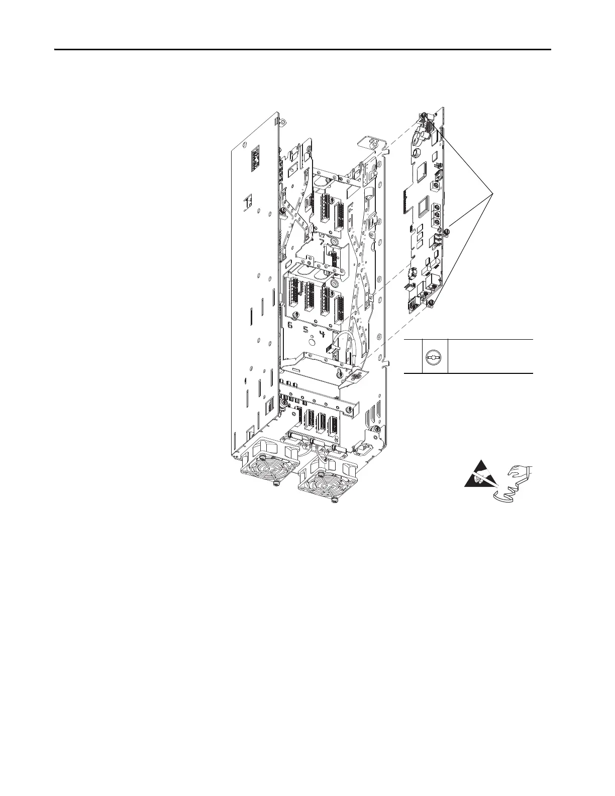
10. Loosen the three captive thumb screws that secure the main control board
to the pod chassis and remove the board.
Install the Main Control Circuit Board
Install the main control circuit board in the reverse order of removal.
10
–
T15 or F - 5 mm (0.19 in.)
0.45 N•m (4 lb•in)
HIM Bezel Not Shown for Clarity Only.
10
=

Table of Contents

Questions and Answers:

Question and Answer IconNeed help?

Do you have a question about the Rockwell Automation PowerFlex 755TL and is the answer not in the manual?

Rockwell Automation PowerFlex 755TL Specifications

General IconGeneral
BrandRockwell Automation
ModelPowerFlex 755TL
CategoryDC Drives
LanguageEnglish

Related product manuals