Rockwell Automation Publication 750-TG100B-EN-P - June 2019 235
Power Bay Components Chapter 9
Guard Removal
When AC input bus bars and fuses or DC link and fuse assemblies are installed
in the power bay, you must remove the upper guard to access other components.
Remove the Guard
Follow these steps to remove and replace the upper guard.
1. Review the Product Advisories on page 14
.
2. Remove power from the system. See Remove Power from the System on
page 15
.
3. Open the corresponding power bay enclosure door.
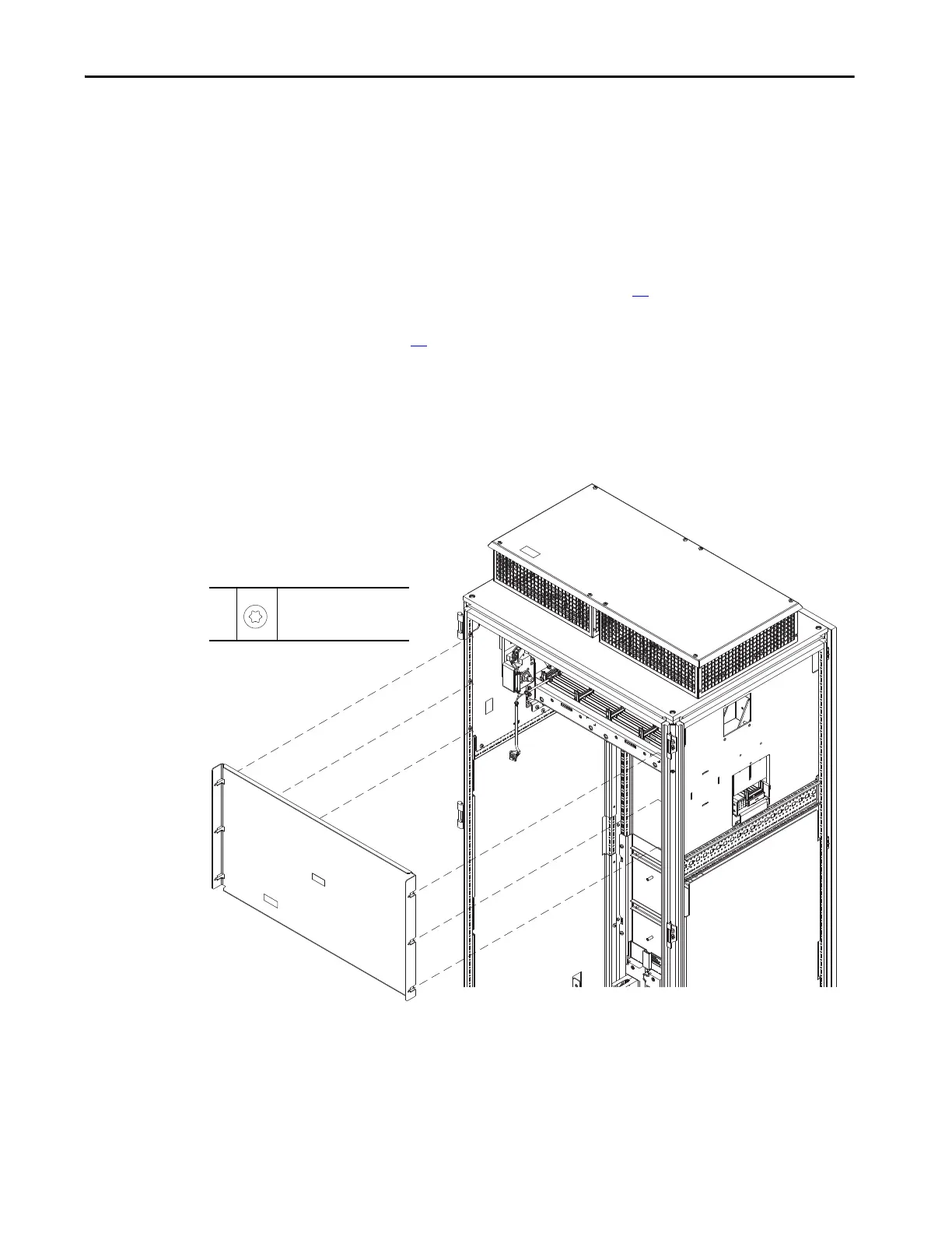
4. Loosen the six M5.5 x 13 mm torx screws that secure the guard from the
enclosure.
Install the Guard
Install the guard in the reverse order of removal.
800 mm Wide Frame 8 Drive Power Bay Shown
4
M5.5 x 13 mm
T25
2.6 N•m (23 lb•in)
 Loading...


