294 Rockwell Automation Publication 750-TG100B-EN-P - June 2019
Chapter 11 Start Up After Repairs
Frames 7…15
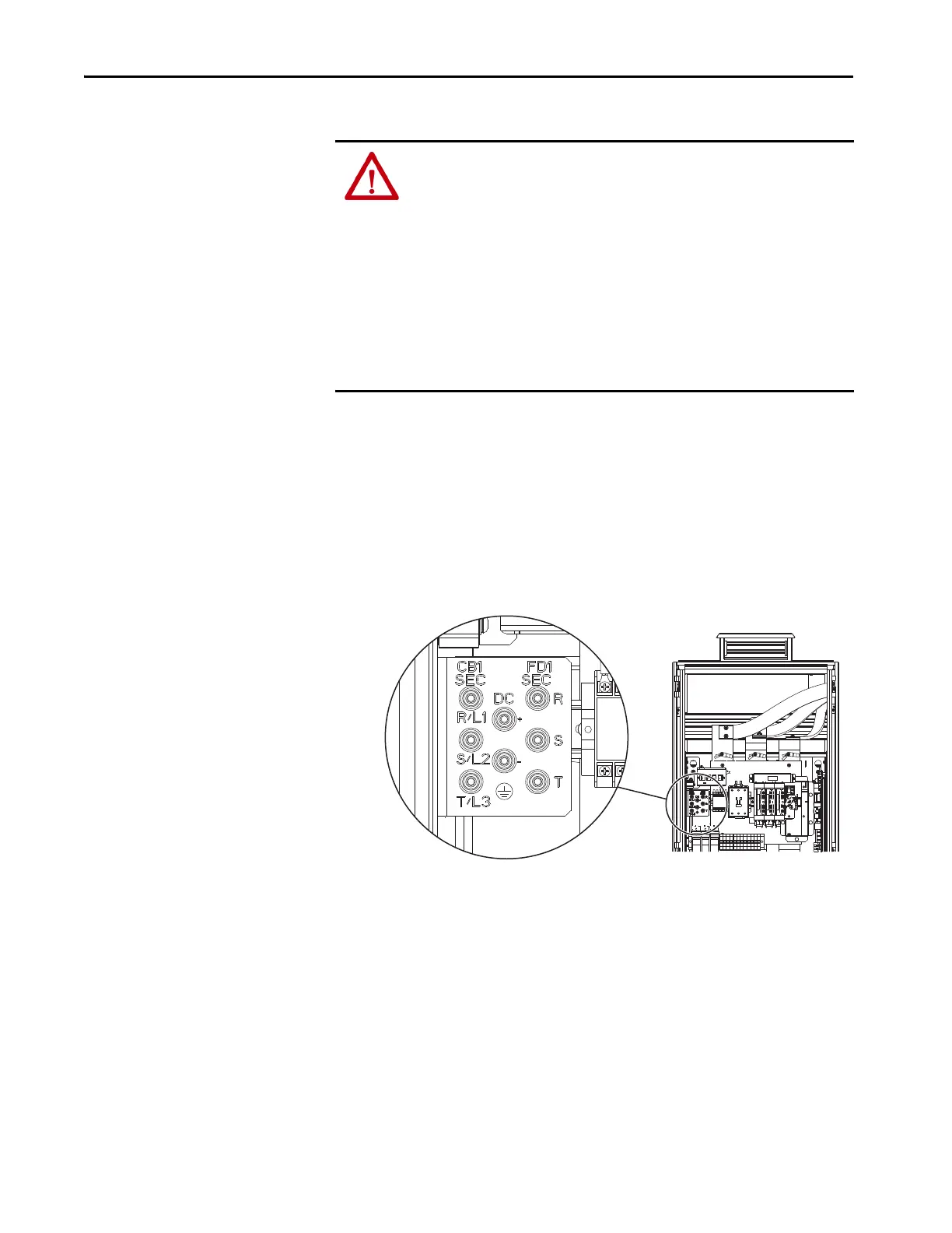
1. For regenerative drives and bus supplies, measure the AC input and DC
bus voltage at the following testpoint sockets in the power bay to verify
that there is no voltage present:
• Use the circuit breaker output (CB1 SEC) testpoints R/L1, S/L2, and
T/L3 to measure L to L and L to chassis GND.
• Use the fused disconnect output (FD1 SEC) testpoints R, S, and T to
measure L to L and L to chassis GND.
• Use the DC bus testpoints +DC and –DC to measure +DC to –DC,
+DC to chassis GND, and –DC to chassis GND.
ATTENTION: To avoid an electric shock hazard, verify that there is no AC input
and DC bus voltage by taking these measurements:
• Verify that there is no AC input voltage present at the circuit breaker by using
the R/L1, S/L2, and T/L3 testpoint sockets in the input bay and by measuring L
to L and L to GND.
• Verify that there is no AC input voltage present at the fused disconnect by using
the R, S, and T testpoint sockets in the input bay and by measuring L to L and L
to GND.
• Verify that there is no DC bus voltage present by using the +DC to –DC test
points in the input bay and by measuring +DC to –DC, +DC to GND, and –DC to
GND.
 Loading...


