148 Rockwell Automation Publication 750-TG100B-EN-P - June 2019
Chapter 7 Control Bay and Control Pod Components
Fiber Transceiver Circuit
Board Replacement
Replace a fiber transceiver circuit board with kit catalog number
20-750-MFTB1-F8.
Remove the Fiber Transceiver Circuit Board
Follow these steps to remove the fiber transceiver circuit board.
1. Review the Product Advisories on page 14
.
2. Remove power from the system. See Remove Power from the System on
page 15
.
3. Open the control bay enclosure door.
4. Remove the control pod cover. See Control Pod Cover Removal on page
146
.
5. Remove the fiber-optic cables for the corresponding fiber transceiver
circuit board from the cable management devices in the control pod.
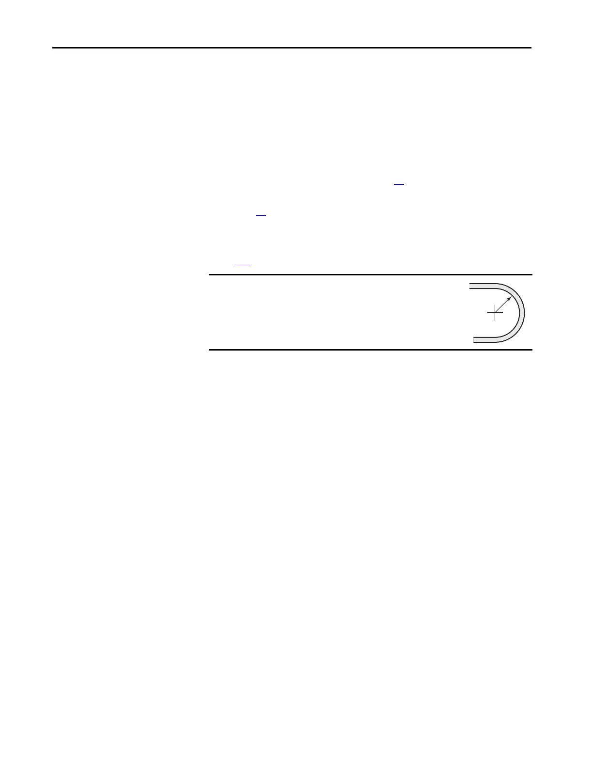
IMPORTANT
Minimum inside bend radius for fiber-optic cable is 50 mm
(2 in.). Any bends with a shorter inside radius can
permanently damage the fiber-optic cable. Signal
attenuation increases as inside bend radius is decreased.
TIP When all or many of the fiber-optic ports are used, it is easier to remove
the fiber transceiver circuit boards from the pod before removing the
fiber-optic cables. However, it is possible to remove the fiber-optic cables
without removing the boards. This procedure assumes that all fiber-optic
ports are used.
 Loading...


