Rockwell Automation Publication 750-TG100B-EN-P - June 2019 157
Control Bay and Control Pod Components Chapter 7
Fiber-optic Interface Circuit
Board Replacement
Replace a fiber-optic interface board with kit catalog number
SK-RM-FIB1-F8 or SK-RM-FIB2-F8.
Remove the Fiber-optic Interface Circuit Board
Follow these steps to remove the fiber-optic interface circuit board.
1. Review the Product Advisories on page 14
.
2. Remove power from the system. See Remove Power from the System on
page 15
.
3. Open the control bay enclosure door.
4. Remove the control pod cover. See Control Pod Cover Removal on page
146
.
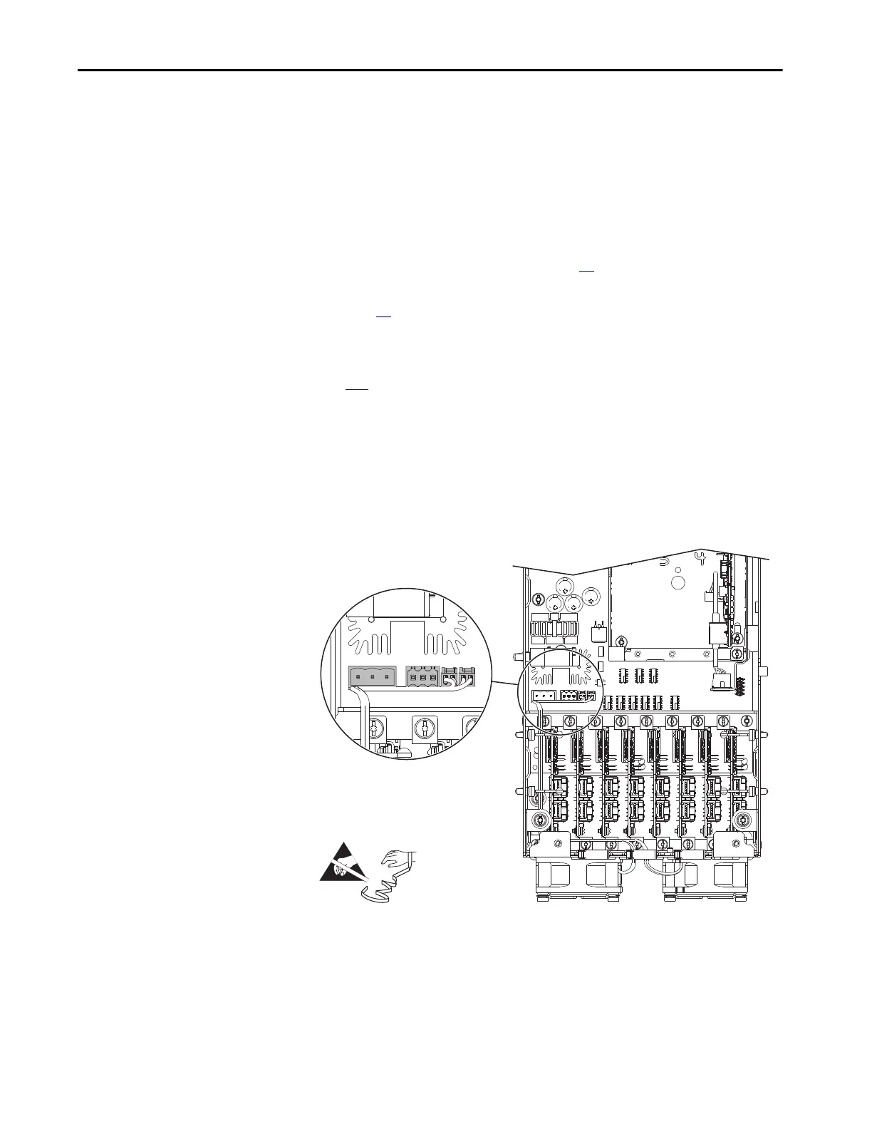
5. Disconnect connector P14 from connector J14 on the fiber-optic interface
board.
6. Disconnect the two fan power supply connectors from connectors J18 and
J25 on the fiber-optic interface board.
7. If installed, disconnect the customer supplied 24V supply power wire
connector P13 from connector J13 on the fiber-optic interface board.
 Loading...


