192 Rockwell Automation Publication 750-TG100B-EN-P - June 2019
Chapter 8 Input Bay Components
Install the AC Precharge TVSS Module
Install the AC precharge TVSS module in the reverse order of removal.
AC Precharge Control
Circuit Board Fuses (FH1)
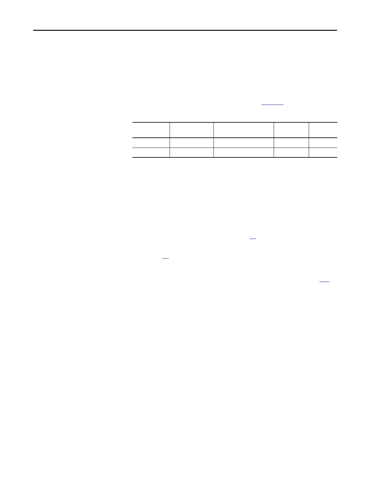
Replacement
Replace the AC precharge control circuit board fuses (labeled FH1) with the
appropriate kit catalog number that is identified in Tab le 1 4
.
Remove the AC Precharge Control Circuit Board Fuses
For frames 8 and 9, the fuse holders (labeled FH1) are located in the AC
precharge module in the input bay. For frames 10…12, the fuse holders (labeled
FH1) are on the control panel in the input bay. Follow these steps to remove and
replace the AC precharge control circuit board fuses.
1. Review the Product Advisories on page 14
.
2. Remove power from the system. See Remove Power from the System on
page 15
.
3. Open the input bay enclosure door.
4. Remove the guard from the enclosure. See Guard Removal on page 183
.
Table 14 - AC Precharge Control Circuit Board Fuse (FH1) Kit Ratings
Frame Size Voltage Class Fuse Kit Cat. No. Fuse Amp
Rating
Quantity
8…12 400V/480V/600V SK-RM-IBCB-FUSE1A-F8 1 3
8…12 690V SK-RM-IBCB-FUSE1B-F9 1 3
 Loading...


