Rockwell Automation Publication 750-TG100B-EN-P - June 2019 123
Frame 7 Components Chapter 6
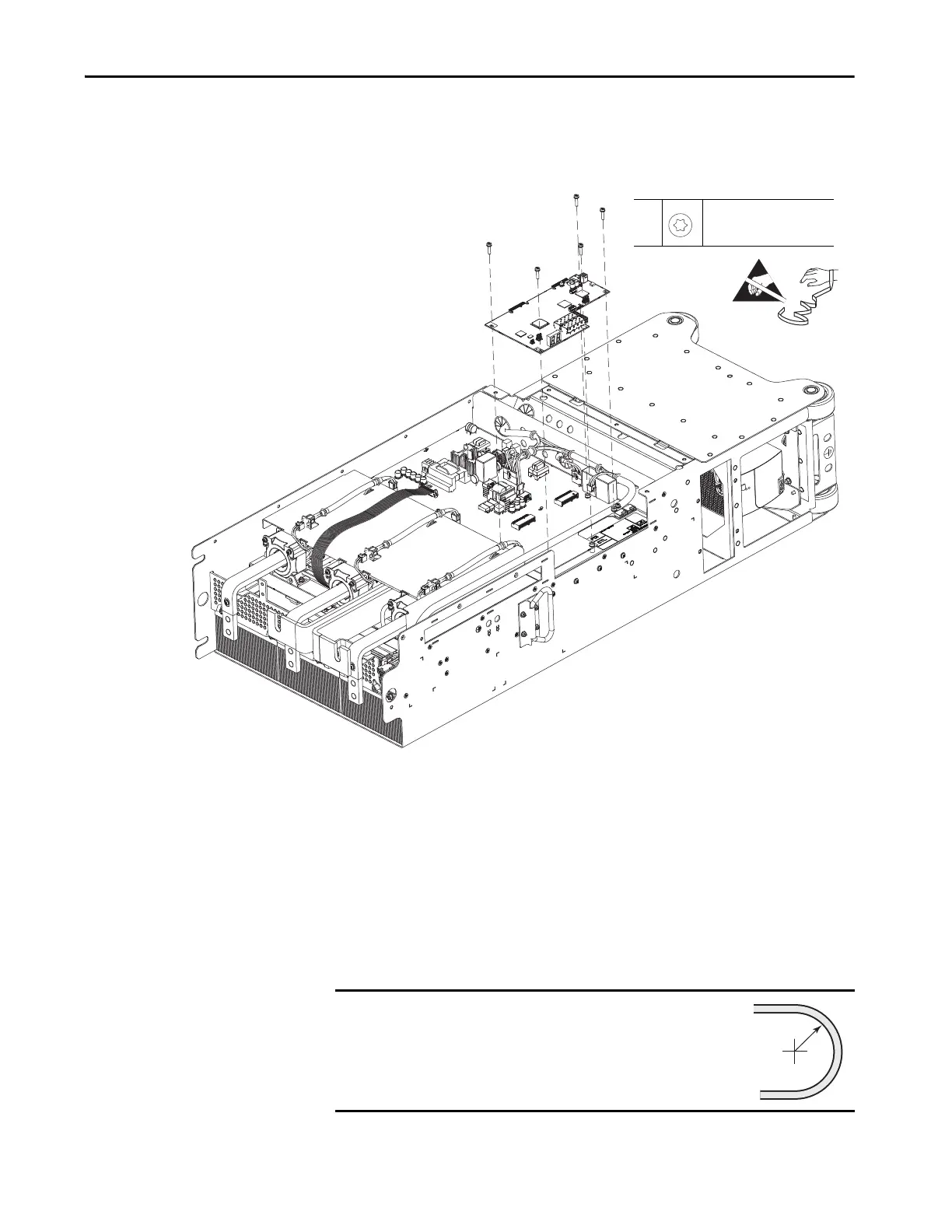
10. Remove the five M4 x 18 mm torx screws that secure the power layer
interface circuit board to the power interface circuit board and remove the
board.
Install the Power Layer Interface Circuit Board
Install the power layer interface circuit board in the reverse order of removal.
When installing the fiber-optic cables:
1. Remove the transceiver from the fiber-optic port on the power layer
interface circuit board.
10
M4 x 18 mm
T20
2.6 N•m (23.0 lb•in)
IMPORTANT
Minimum inside bend radius for fiber-optic cable is 50 mm
(2 in.). Any bends with a shorter inside radius can
permanently damage the fiber-optic cable. Signal
attenuation increases as inside bend radius is decreased.
 Loading...


