120 Rockwell Automation Publication 750-TG100B-EN-P - June 2019
Chapter 6 Frame 7 Components
Install the Power Module in the Enclosure
Install the power module into the enclosure in the reverse order of removal.
When installing the fiber-optic cables:
1. Remove the transceiver from the fiber-optic port on the power layer
interface circuit board.
2. Without bending the cable to a radius less than 50 mm (2 in.), fully insert
the fiber-optic cable into the transceiver.
3. Insert the transceiver and fiber-optic cable into the port on the board, until
you hear an audible ‘click.’
Power Layer Interface
Circuit Board Replacement
Replace a power layer interface circuit board with kit catalog number
SK-RM-PLI1-F7.
Remove the Power Layer Interface Circuit Board
Follow these steps to remove the power layer interface circuit board.
1. Review the Product Advisories on page 14
.
2. Remove power from the system. See Remove Power from the System on
page 15
.
3. Open the enclosure door.
4. Remove the protective guard. See Remove the Protective Guard on page
110
.
5. Remove the power module from the enclosure. See Remove the Power
Module from the Enclosure on page 113
.
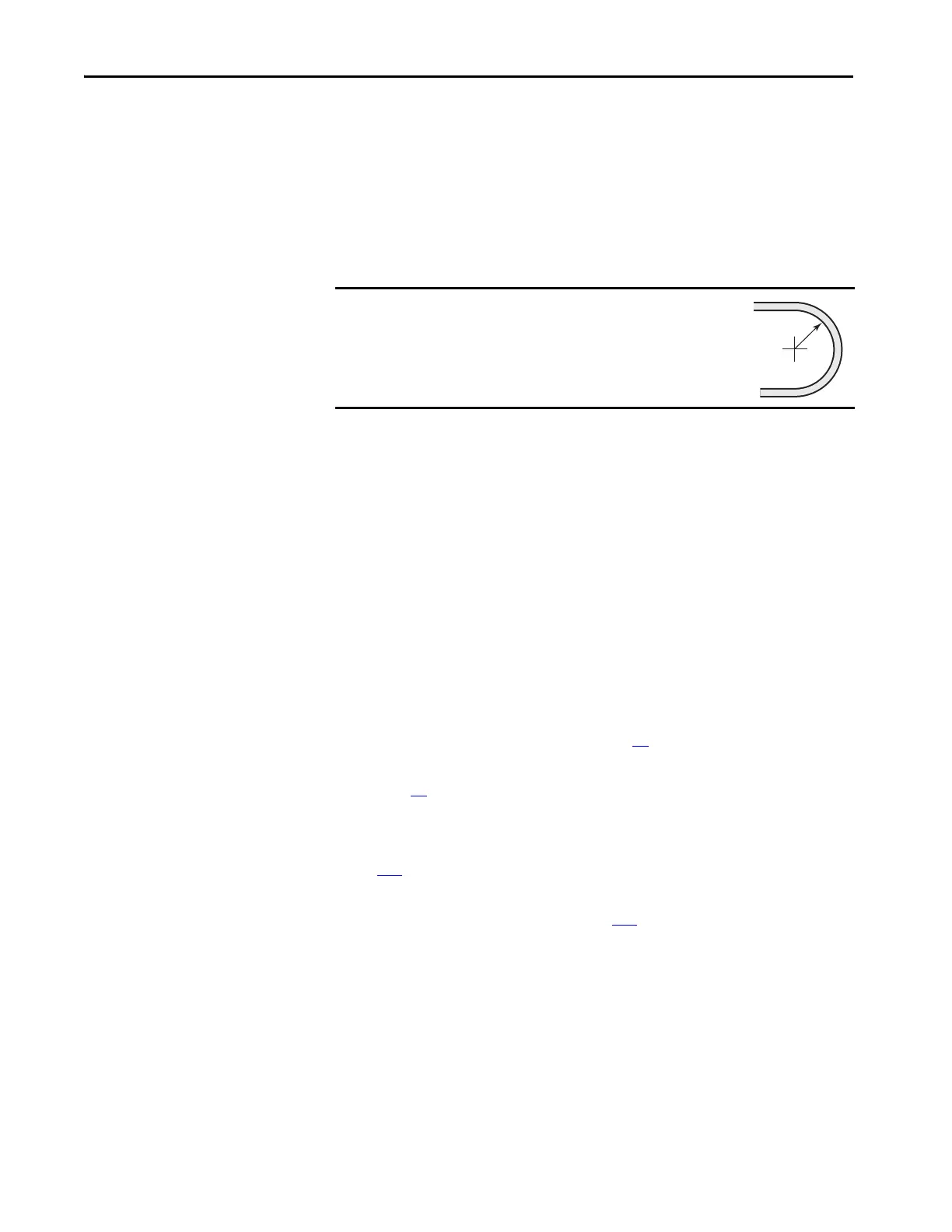
IMPORTANT
Minimum inside bend radius for fiber-optic cable is 50 mm
(2 in.). Any bends with a shorter inside radius can
permanently damage the fiber-optic cable. Signal
attenuation increases as inside bend radius is decreased.
 Loading...


