90 Rockwell Automation Publication 750-TG100B-EN-P - June 2019
Chapter 5 Frame 6 Components
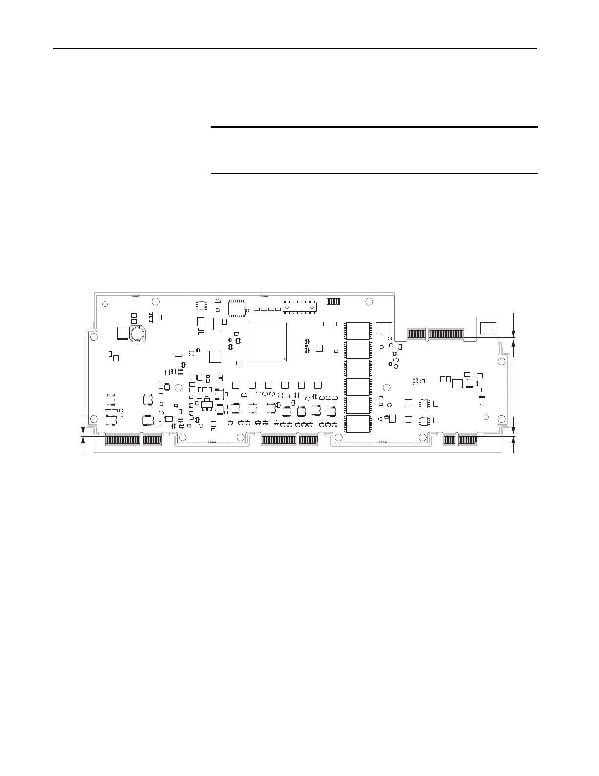
Install the Power Feedback Circuit Board and Bracket
Follow these steps to install the power feedback circuit board and bracket.
1. Apply a dielectric grease to all edge connectors on the power feedback
circuit board, according to these requirements:
• PolySi PST-576 is the only approved dielectric grease for use.
• Apply the dielectric grease to a uniform thickness of 1…2 mm on both
sides of the connector.
• Apply the dielectric grease to a minimum of 2 mm beyond the edge of
the gold connectors (ideally in contact with the conformal coating).
2. Install the power feedback board and bracket in the reverse order of
removal.
• Verify that the connector on the right side of the control pod seats
properly on the edge connector on the top of the power feedback board
when you re-install the control pod.
IMPORTANT You must apply a PolySi PST-576 non-silicone, dielectric connector grease to
the edge connectors on the new power feedback circuit board before
installation.
2 mm (0.08 in.)
2 mm (0.08 in.)
2 mm (0.08 in.)
 Loading...


