Rockwell Automation Publication 750-TG100B-EN-P - June 2019 241
Power Bay Components Chapter 9
17. To release the LCL filter module, remove the two remaining M10 x 20 mm
screws.
18. Remove the power modules from the enclosure.
Install the Power Module in the Enclosure
Install the power module into the enclosure in the reverse order of removal.
When installing the fiber-optic cables:
1. Remove the transceiver from the fiber-optic port on the power layer
interface circuit board.
2. Without bending the cable to a radius less than 50 mm (2 in.), fully insert
the fiber-optic cable into the transceiver.
3. Insert the transceiver and fiber-optic cable into the port on the board, until
you hear an audible ‘click.’
DC Link Fuses Replacement
Replace the DC link fuses with the appropriate kit catalog number that is
identified in Tab le 21
.
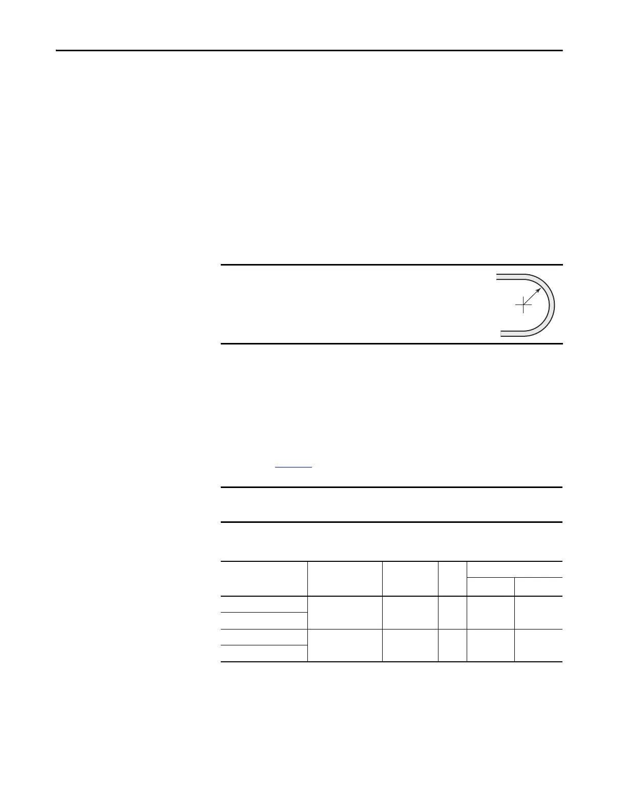
IMPORTANT
Minimum inside bend radius for fiber-optic cable is 50 mm
(2 in.). Any bends with a shorter inside radius can
permanently damage the fiber-optic cable. Signal
attenuation increases as inside bend radius is decreased.
IMPORTANT It is recommended that you replace both DC link fuses for each power module
installed.
Table 21 - DC Link/Fuse Assembly Fuse Ratings
DC Link/Fuse Assembly
Kit Cat. No.
Fuse Kit Cat. No Voltage Class Fuses
Per
Kit
Fuse Size
Amps/Leg 1/Leg
20-750-MDCL1-CD-F8M SK-RM-DCFUSE1-F8 400/480V AC 2 1400 170M6467
20-750-MDCL2-CD-F8M
20-750-MDCL1-EF-F8M SK-RM-DCFUSE2-F8 600/690V AC 2 1100 170M6499
20-750-MDCL2-EF-F8M
 Loading...


