4-32 FI SYSTEM
“C12” CKP SENSOR CIRCUIT MALFUNCTION
DETECTED CONDITION POSSIBLE CAUSE
No CKP sensor signal for 3 seconds at engine • Metal particles or foreign material being
cranking. attached on the CKP sensor and rotor tips.
• CKP sensor circuit open or short.
• CKP sensor malfunction.
• ECM malfunction.
INSPECTION
• Remove the frame side covers, left and right. (6-3)
• Lift the fuel tank little. ( 4-48)
Turn the ignition switch OFF.
Check the CKP sensor coupler for loose or poor contacts.
If OK, then measure the CKP sensor resistance.
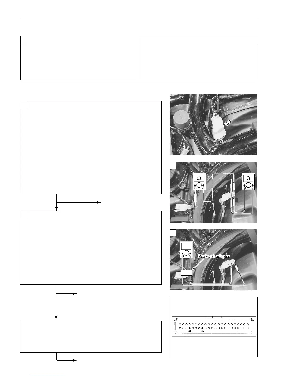
Disconnect the CKP sensor coupler and measure the re-
sistance.
CKP sensor resistance: 134 – 202
ΩΩ
ΩΩ
Ω
(Blue – Yellow)
If OK, then check the continuity between each terminal
and ground.
CKP sensor continuity:
∞Ω∞Ω
∞Ω∞Ω
∞Ω (Infinity)
Blue – Ground
(
Yellow – Ground
)
\ 09900-25008: Multi circuit tester
V Tester knob indication: Resistance (
ΩΩ
ΩΩ
Ω)
No Replace the CKP sensor
with a new one.
Ye s
Disconnect the CKP sensor coupler.
Crank the engine a few seconds with the starter motor, and
measure the CKP sensor peak voltage at the coupler.
CKP sensor peak voltage: More than 2.7 V
(Blue – Yellow)
Repeat the above test procedure a few times and mea-
sure the highest peak voltage.
If OK, then measure the CKP sensor peak voltage at the
ECM terminals. (N+/N– or P/T)
\ 09900-25008: Multi circuit tester
W Tester knob indication: Voltage (
)
No Loose or poor contacts on the CKP
sensor coupler or ECM coupler.
Clean the CKP sensor and rotor tips
or replace the CKP sensor with a
new one.
Ye s
Blue or Yellow wire open or shorted to ground, or poor P or T
connection. ( 4-22)
If wire and connection are OK, intermittent trouble or faulty ECM.
Recheck each terminal and wire harness for open circuit and
poor connection. ( 4-4)
Replace the ECM with a new one,
and inspect it again.
2
1
ECM couplers
V
2
1
 Loading...


