FI SYSTEM 4-67
SENSORS
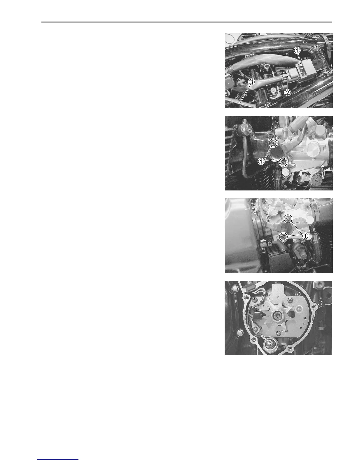
IAP SENSOR INSPECTION
The intake air pressure sensor is located at the upper frame be-
tween the tubes. ( 4-33)
IAP SENSOR REMOVAL/INSTALLATION
• Lift and support the fuel tank. ( 4-48)
• Remove the IAP sensor 1 and disconnect the coupler 2 and
vacuum hose 3.
• Installation is in the reverse order of removal.
TP SENSOR INSPECTION
The throttle position sensor is installed on the No.1 throttle body.
( 4-35)
TP SENSOR REMOVAL/INSTALLATION
• Lift and support the fuel tank. ( 4-48)
• Remove the TP sensor setting screws 1 and disconnect its
coupler.
• Install the TP sensor to the No.1 throttle body. Refer to page 4-
64 for TP sensor setting procedure.
STP SENSOR INSPECTION
The secondary throttle position sensor is installed on the No. 4
throttle body. (4-43)
STP SENSOR REMOVAL/INSTALLATION
• Lift and support the fuel tank. (4-48)
• Remove the STP sensor setting screws 1 and disconnect its
coupler.
• Install the STP sensor to the No. 4 throttle body. Refer to page
4-62 for STP sensor setting procedure.
CKP SENSOR INSPECTION
The signal rotor is mounted on the right end of the crankshaft,
and the crankshaft position sensor (Pick-up coil) is installed on
the right side of the crankcase. ( 4-32)
CKP SENSOR REMOVAL/INSTALLATION
( 3-15 and -69)
 Loading...


