FI SYSTEM 4-41
INSPECTION
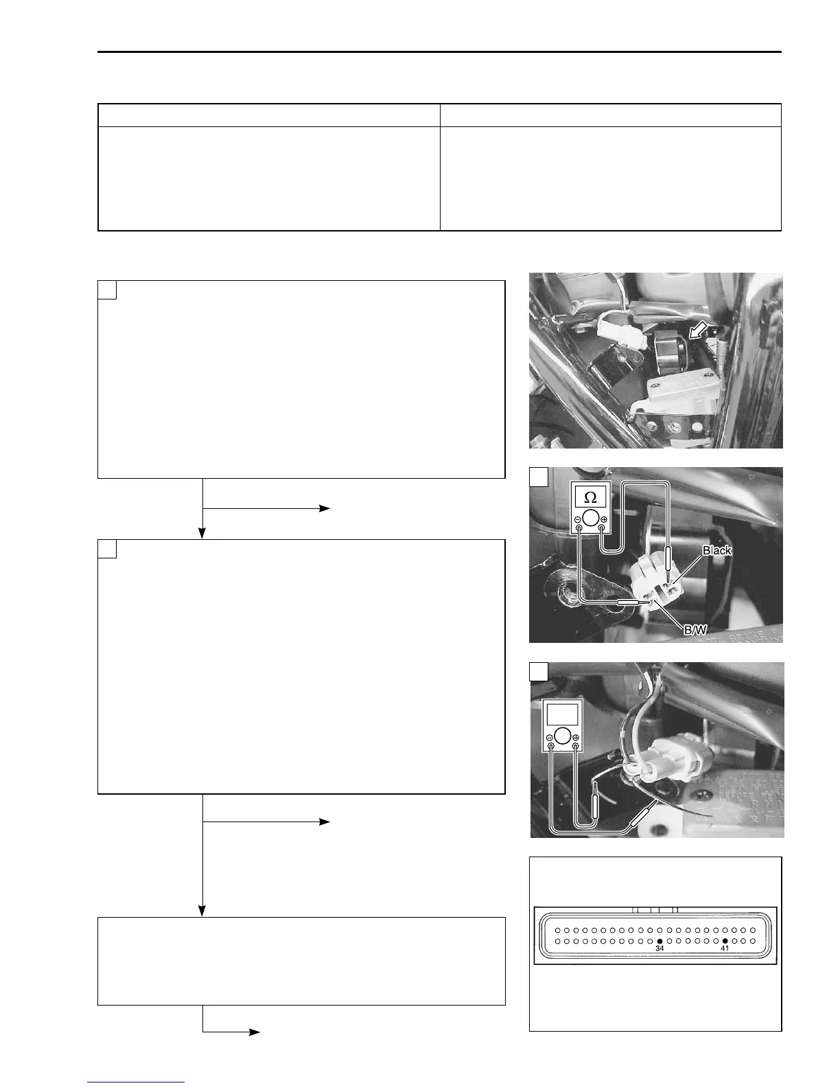
• Remove the right frame side cover. ( 6-3)
Turn the ignition switch OFF.
Check the TO sensor coupler for loose or poor contacts.
If OK, then measure the TO sensor resistance.
Disconnect the TO sensor coupler.
Measure the resistance between Black and B/W wire ter-
minals.
TO sensor resistance: 60 – 64 k
ΩΩ
ΩΩ
Ω
(Black – B/W)
\ 09900-25008: Multi circuit tester
V Tester knob indication: Resistance (
ΩΩ
ΩΩ
Ω)
No Replace the TO sensor
with a new one.
Ye s
Connect the TO sensor coupler.
Insert the copper wires to the wire lead coupler.
Turn the ignition switch ON.
Measure the voltage at the wire side coupler between
Brown and B/Br wires.
TO sensor voltage: Approx. 3.8 V (Brown – B/Br)
Also, measure the voltage when leaning of the motorcycle.
Dismount the TO sensor from its bracket and measure the
voltage when it is leaned more than 43°, left and right,
from the horizontal level.
TO sensor voltage: 0 V (Brown – B/Br)
\ 09900-25008: Multi circuit tester
W Tester knob indication: Voltage (
)
No Loose or poor contacts on
the ECM coupler.
Open or short circuit in the
Brown wire or B/Br wire.
Replace the TO sensor
with a new one.
Ye s
Brown or B/Br wire open or shorted to ground, or poor a or X
connection. ( 4-22)
If wire and connection are OK, intermittent trouble or faulty ECM.
Recheck each terminal and wire harness for open circuit and
poor connection. ( 4-4)
Replace the ECM with a new
one, and inspect it again.
“C23” TO SENSOR CIRCUIT MALFUNCTION
DETECTED CONDITION POSSIBLE CAUSE
No TO sensor signal for more than 2 seconds, • TO sensor circuit open or short.
after ignition switch turns ON. • TO sensor malfunction.
Sensor voltage high. • ECM malfunction.
Sensor Voltage < 3.90 V
(
without the above value.
)
2
1
ECM coupler
1
2
 Loading...


