FI SYSTEM 4-39
V
Red
“C22” AP SENSOR CIRCUIT MALFUNCTION
DETECTED CONDITION POSSIBLE CAUSE
Low pressure and low voltage. • Clogged air passage with dust.
High pressure and high voltage. • Red wire circuit open or shorted to ground.
0.20 V
Sensor Voltage < 4.80 V • B/Br or G/Y wire circuit shorted to ground.
(
without the above range.
)
• AP sensor malfunction.
NOTE:
• ECM malfunction.
Note that atmospheric pressure varies depending
on weather conditions as well as altitude.
Take that into consideration when inspecting voltage.
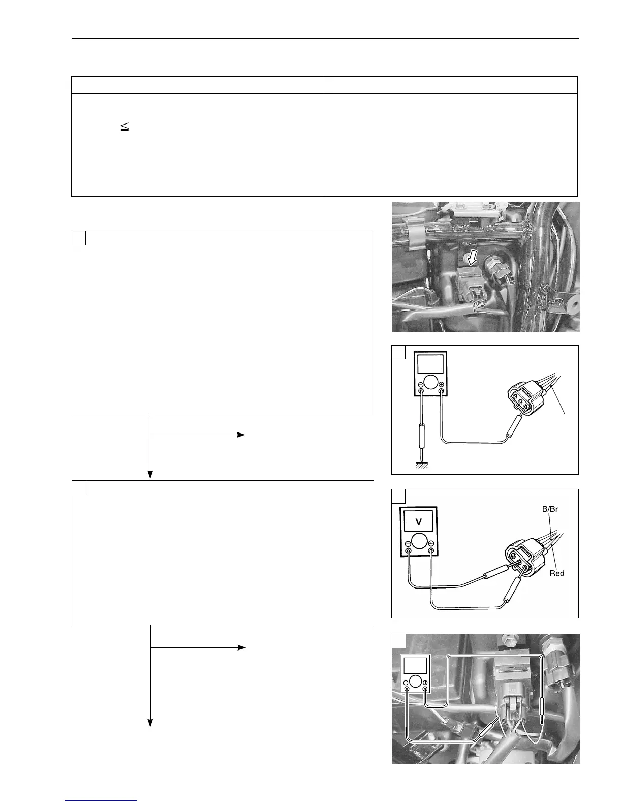
INSPECTION
• Remove the right frame side cover. (6-3)
Turn the ignition switch OFF.
Check the AP sensor coupler for loose or poor contacts.
If OK, then measure the AP sensor input voltage.
Turn the ignition switch ON.
Disconnect the AP sensor coupler.
Measure the voltage between Red wire and ground.
If OK, then measure the voltage between Red wire and B/
Br wire.
AP sensor input voltage: 4.5 – 5.5 V
(
+Red – -Ground
)
+Red – -B/Br
\ 09900-25008: Multi circuit tester
W Tester knob indication: Voltage (
)
No Loose or poor contacts on
the ECM coupler.
Open or short circuit in the
Red wire or B/Br wire.
Ye s
Connect the AP sensor coupler.
Insert the copper wires to the lead wire coupler.
Turn the ignition switch ON.
Measure the AP sensor output voltage at the wire side
coupler between G/Y and B/Br wires.
AP sensor output voltage: Approx. 4.0 V
at 760 mmHg (100 kPa)
(+G/Y – -B/Br)
\ 09900-25008: Multi circuit tester
W Tester knob indication: Voltage (
)
No
Check the air passage
for clogging.
Open or short circuit in the
G/Y wire.
Replace the AP sensor
with a new one.
Ye s
1
1
1
2
2
 Loading...


