4-64 FI SYSTEM
W
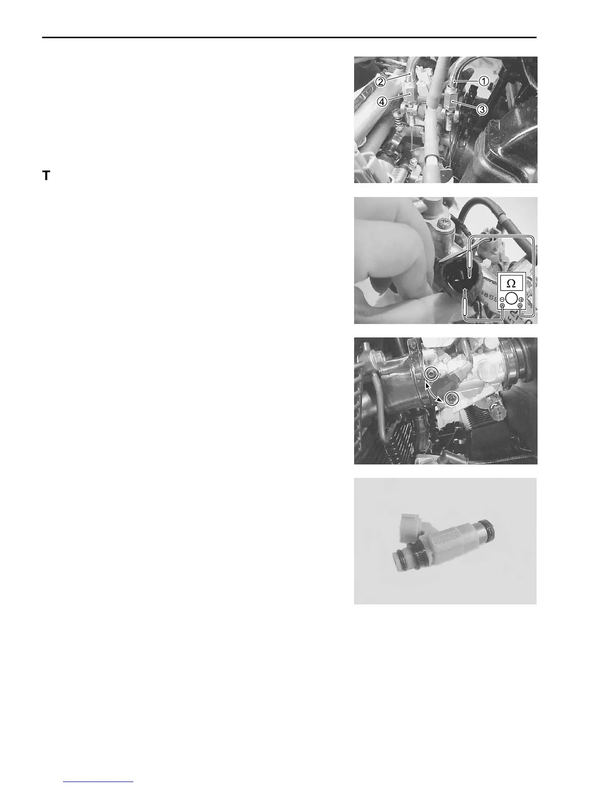
TP SENSOR ADJUSTMENT
• After checking or adjusting the throttle valve synchronization,
measure the TP sensor resistance and adjust the TP sensor
positioning as follows:
• After warming up engine, adjust the idling speed to 1 100 ±
100 rpm.
• Stop the warmed-up engine and disconnect the TP sensor lead
wire coupler. (4-35)
• Measure the resistance between yellow and black wires.
TP sensor setting resistance: Approx. 1.1 kΩ
(+ Yellow – - Black)
\ 09900-25008: Multi circuit tester
V Tester knob indication: Resistance (
ΩΩ
ΩΩ
Ω)
• Loosen the TP sensor mounting screws.
• Adjust the TP sensor until resistance is within specification and
tighten the TP sensor mounting screws.
\ 09930-11960: Torx wrench
" TP sensor mounting screw: 3.5 N
.
m
(0.35 kgf
.
m, 2.5 lb-ft)
FUEL INJECTOR INSPECTION
The fuel injector can be checked without removing it from the
throttle body.
Refer to page 4-46 for details.
FUEL INJECTOR REMOVAL
• Lift and support the fuel tank with a proper stay. ( 4-48)
• With battery negative cable disconnected, disconnect the in-
jector couplers.
• Remove the fuel delivery pipe assembly. ( 4-56)
• Remove the fuel injectors No.1, No.2, No.3 and No.4.
( 4-57)
INSPECTION
Check fuel injector filter for evidence of dirt and contamination. If
present, clean and check for presence of dirt in the fuel lines and
fuel tank.
FUEL INJECTOR INSTALLATION
• Apply thin coat of the engine oil to new injector cushion seals
and O-rings.
• Install the injector by pushing it straight to the throttle body.
Never turn the injector while pushing it. ( 4-61)
THROTTLE BODY INSTALLATION
Installation is in the reverse order of removal. Pay attention to the
following points:
• Connect the throttle pulling cable 1 and throttle returning cable
2 to the throttle cable drum.
• Adjust the throttle cable play with the cable adjusters 3 and
4.
Refer to page 2-15 for details.
 Loading...


