FI SYSTEM 4-35
“C14” TP SENSOR CIRCUIT MALFUNCTION
DETECTED CONDITION POSSIBLE CAUSE
Signal voltage low or high. • TP sensor maladjusted.
Difference between actual throttle opening and • TP sensor circuit open or short.
opening calculated by ECM in larger than specified • TP sensor malfunction.
value. • ECM malfunction.
0.20 V
Sensor Voltage < 4.80 V
(
without the above range.
)
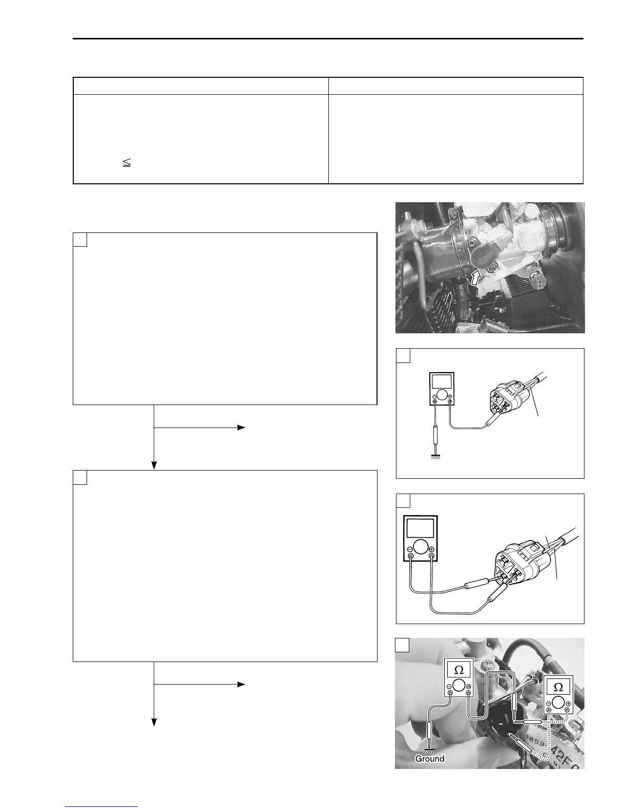
INSPECTION
• Lift and support the fuel tank with a proper stay. (4-48)
Turn the ignition switch OFF.
Check the TP sensor coupler for loose or poor contacts.
If OK, then measure the TP sensor input voltage.
Disconnect the TP sensor coupler (Black color).
Turn the ignition switch ON.
Measure the voltage at the Red wire and ground.
If OK, then measure the voltage at the Red wire and B/Br wire.
TPS sensor input voltage: 4.5 – 5.5 V
(
+Red – -Ground
)
+Red – -B/Br
\ 09900-25008: Multi circuit tester
W Tester knob indication: Voltage (
)
No Loose or poor contacts on
the ECM coupler.
Open or short circuit in the
Red wire or B/Br wire.
Ye s
Turn the ignition switch OFF.
Disconnect the TP sensor coupler (Black color).
Check the continuity between Yellow wire and ground.
TP sensor continuity:
∞Ω∞Ω
∞Ω∞Ω
∞Ω (Infinity)
(Yellow wire – Ground)
If OK, then measure the TP sensor resistance at the cou-
pler (between Yellow and Black wires).
Turn the throttle grip and measure the resistance.
TP sensor resistance
Throttle valve is closed: Approx. 1.1 k
ΩΩ
ΩΩ
Ω
Throttle valve is opened: Approx. 4.3 k
ΩΩ
ΩΩ
Ω
\ 09900-25008: Multi circuit tester
V Tester knob indication: Resistance (
ΩΩ
ΩΩ
Ω)
No
Reset the TP sensor
position correctly.
Replace the TP sensor
Yes with a new one.
1
2
V
B/Br
Red
V
Red
Ground
1
1
2
 Loading...


