5-3
IM 04L51B01-01EN
Maintenance and Troubleshooting
5
Note
For thermocouple inputs, you must measure the temperature of the input terminal and apply a
voltage taking into account the reference junction temperature.
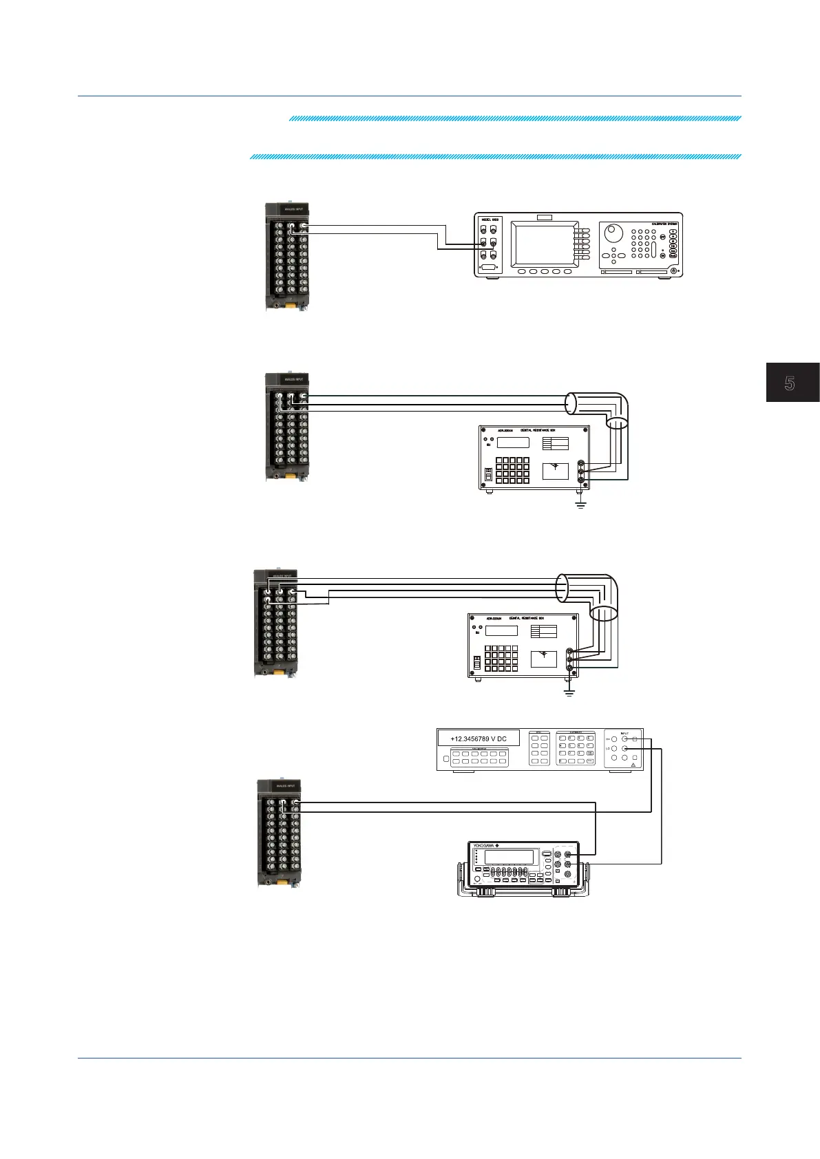
DC Voltage Measurement
CH1
Hi
Lo
DC voltage/current standard
Wiring to the first channel
of the module to calibrate
(Channel ��01)
+
–
Temperature or Resistance Measurement Using an RTD
Three-wiresystem
b
B
A
CH1
H
L
G
Resistance standard
The resistance of three
lead wires must be equal.
Wiring to the first channel
of the module to calibrate
(Channel ��01)
Four-wiresystem/resistance
The resistance of four lead
wires must be equal.
Wiring to the first channel
of the module to calibrate
(channel □□01)
H
L
G
C
I
B
A
Current(mA)Input
+
-
CH1
+
-
GS200
DC VOLTAGE/CURRENT SOURCE
SAMPLE
ERROR
REPEAT
STORE
REMOTE
ERROR
LOCAL
ESC
POWER
NUM
LOCK
1 2 3 4 5
BS
RANGE
6 7 8 9 0
UTILITY
SETUP
LIMIT
MEASURE
PROGRAM
END
DEL
HOLD
STEP
RUN
PROGRAM
OUTPUT
V
mV
mA
SRQ
ENTER
SENSE OUTPUT
32V
MAX
0.5V
MAX
32V
200mA
MAX
Hi
Lo
42V
10mA
PEAK
G
G TERM 250 V PEAK TO
Digital multimeter
.
5.1 Maintenance

 Loading...