<7. Startup>
7-2
IM 11M12G01-02EN 1sh Edition : Mar. 25, 2021-00
7.2 Checking Piping and Wiring Connections
Check that the piping and wiring connections have been properly completed in accordance with
Chapter
“4. Piping” and Chapter “5. Wiring”
7.3 Checking Valve Setup
Set up valves and associated components used in the analyzer system as follows:
(1) If a stop valve is used in the detector’s calibration gas inlet, fully close this valve.
(2) If instrument air is used as the reference gas, adjust the air-set secondary pressure so that
plus approx. 150 kPa when a check valve is used, maximum pressure rating is 300 kPa) is
completing the valve setup, be sure to tighten the lock nut.
NOTE
unit.
7.4 Supplying Power to the Converter
CAUTION
To avoid temperature changes around the detector, it is recommended that (rather than turning it
where it is used periodically.
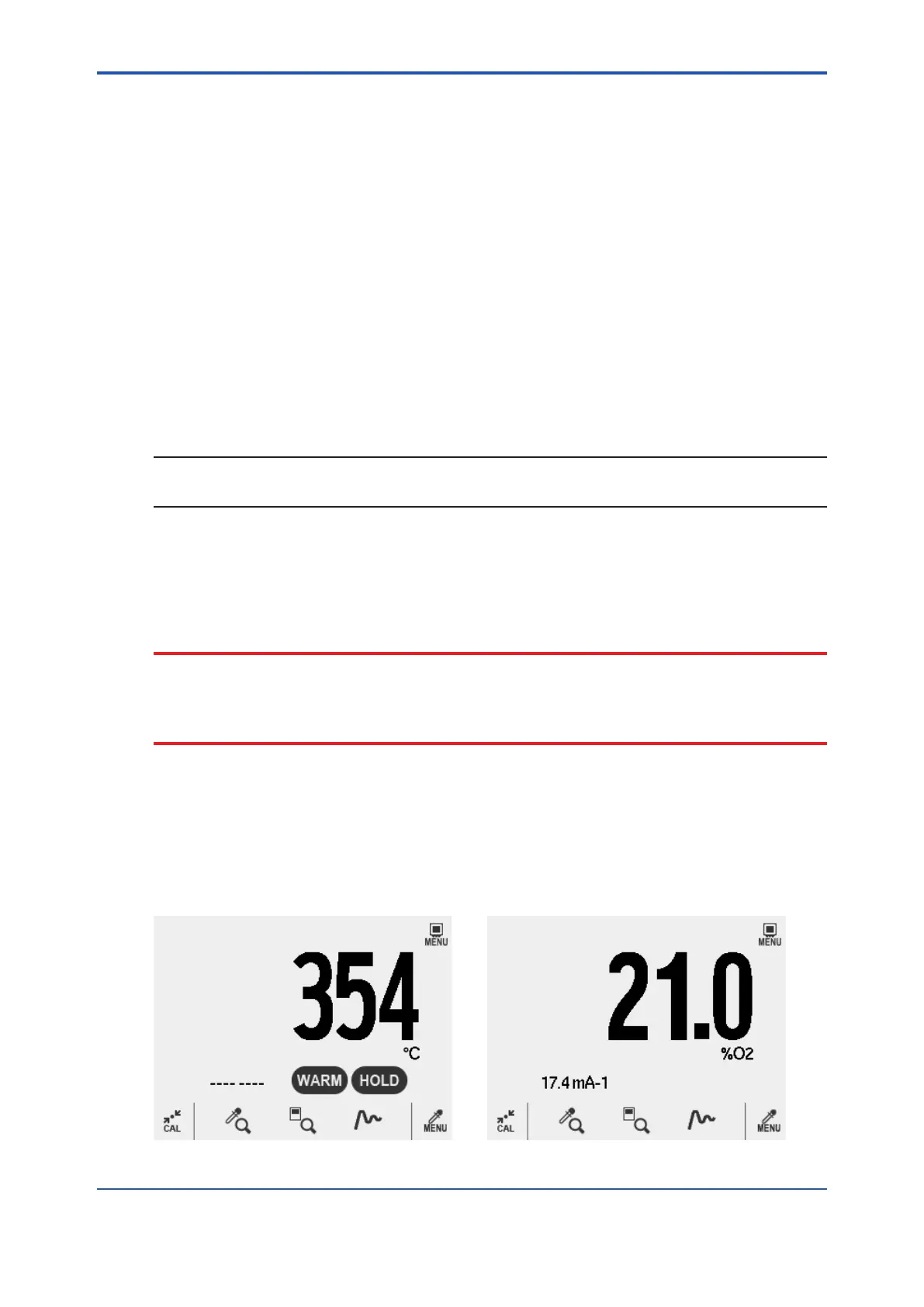
Supply power to the converter. A display as in Figure 7.2, which indicates the detector’s sensor
temperature, then appears. As the heat in the sensor increases, the temperature gradually rises
to 750°C. This takes about 20 minutes after the power is turned on, depending somewhat on the
ambient temperature and the sample gas temperature.
After the sensor temperature has stabilized at 750°C, the converter is in measurement mode.
The display panel then displays the oxygen concentration as in Figure 7.3. This is called Home
screen.
Figure 7.2 Display During Warm-up Figure 7.3 Measurement Mode Display
 Loading...


