<3. Installation>
3-13
IM 11M12G01-02EN 1sh Edition : Mar. 25, 2021-00
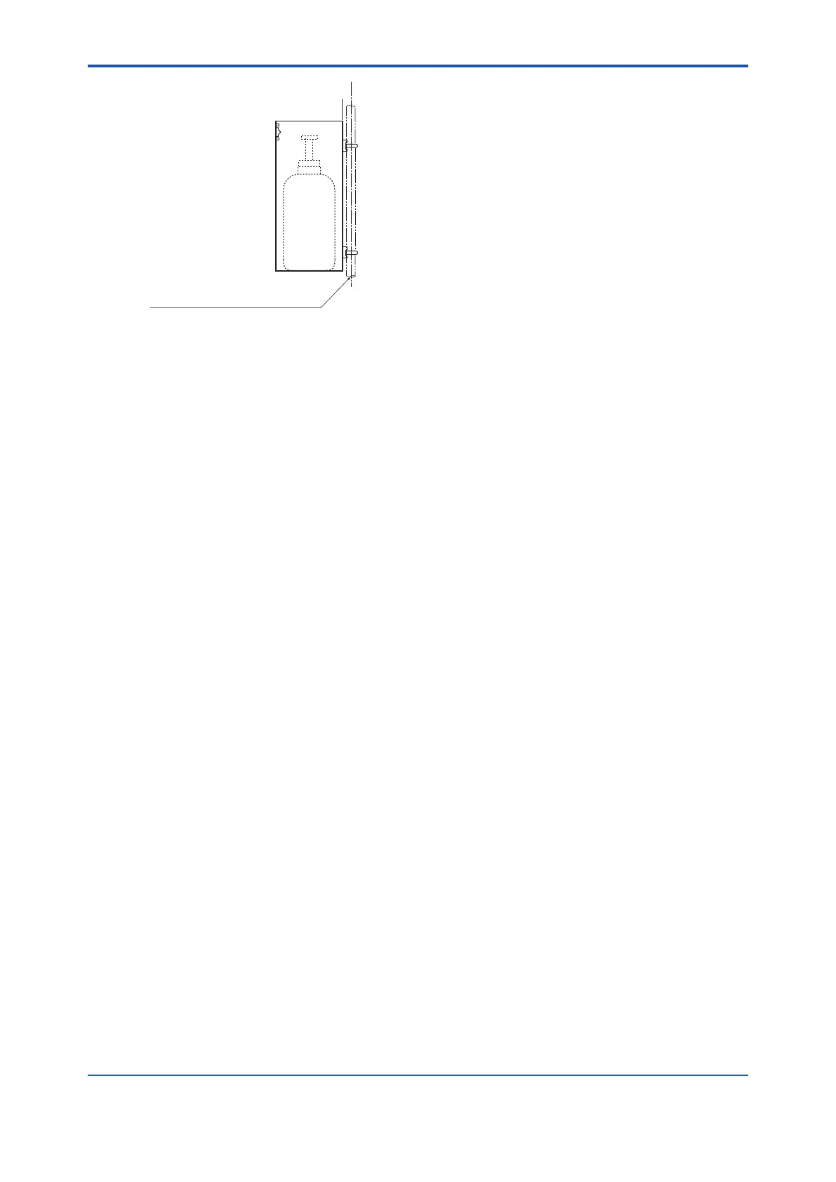
F3-16E.ai
A pipe to be mounted
(nominal JIS 50A : O.D. 60.5 mm)
Figure 3.20 Pipe Mounting
3.7 Insulation Resistance Test
Even if the testing voltage is not so great that it causes dielectric breakdown, testing may cause
deterioration in insulation and a possible safety hazard. Therefore, conduct this test only when it
is necessary.
The applied voltage for this test shall be 500 V DC or less. The voltage shall be applied for as
Remove wiring from the converter and the detector.
(1) Connect a Insulation Resistance meter (Power Supply OFF) between the crossover wiring
and the grounding terminal. For polarity, set the crossover wiring to (+) and the ground
terminal to (-).
(2) Measure Insulation Resistance by setting Power Supply of Insulation Resistance meter to
ON.
the crossover wiring and grounding. Discharge the battery for more than a second. Do not
touch the terminals with bare hands while discharging.
(4) You can perform similar tests between the heater terminal and ground, between contact
output terminal and ground, and between the analogue output terminal and ground.
(5) Contact input terminal/sensor input terminal is isolated, but Insulation Resistance testing is
abort because the voltage of the surge protection arrester between the terminal and ground
is low.
(6) After completing all tests, put back the wiring in place.
 Loading...


