<10. Other Functions>
10-40
IM 11M12G01-02EN 1sh Edition : Mar. 25, 2021-00
Check the Trend graph display to see that the measured value is stabilized. Then press the
[Enter] key. The Manual calibration display shown in Figure 10.16 appears.
nut, be sure to tighten the lock nut to prevent any leakage of span gas into the sensor during
measurement.
(1) (2)
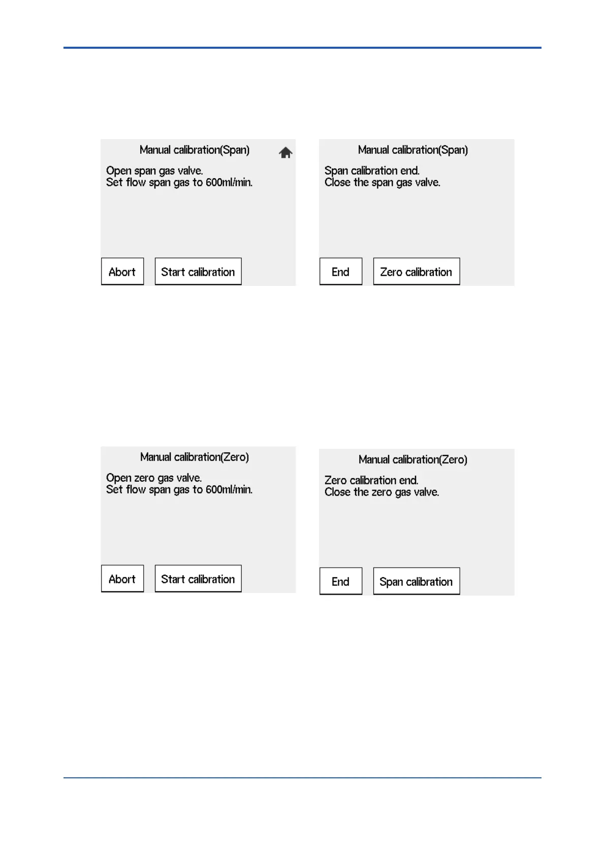
Figure 10.34 Span Gas Manual calibration
10.12.3 Operating the Zero Gas Flow Setting Valve
(1) When the display shown in Figure 10.19 appears during calibration, open the zero gas
rotate the valve shaft, if the valve has a lock nut loosen the lock nut and slowly turn it
If the sample gas pressure is extremely high, adjust the sample gas pressure to obtain
pressures (listed in Table 10.7) ± 10%.
Figure
10.35 Zero Gas Manual calibration
Check the Trend graph display to see that the measured value is stabilized. Then press the
[Enter] key. The Manual calibration display shown in Figure 10.20 appears.
be sure to tighten the lock nut to prevent the any leakage of the zero gas into the detector
because the valve may become loose during measurement.
10.12.4 Operation After Calibration
No special operation of the instrument is needed after calibration. However, it is recommended
that the pressure reducing valve for the zero gas cylinders be closed because calibration is not
 Loading...


