<4. Piping>
4-1
IM 11M12G01-02EN 1sh Edition : Mar. 25, 2021-00
4. Piping
Zirconia Oxygen/Humidity Analyzer.
• Ensure that each check valve, stop valve and joint used for piping do not allow leakage.
Especially, if there is any leakage of the calibration gas from pipes and joints, it may cause
clogging of the pipes or incorrect calibration.
• Be sure to conduct leakage test after piping.
removing any dust, oil mist and the like) for the reference gas.
• When the instrument uses natural convection for reference gas, ambient air near the
ambient humidity changes or the like. If more accurate analysis is necessary, use instrument
like) for reference gas.
Stable analyzing can be conducted when using instrument air.
4.1 Piping for System 1
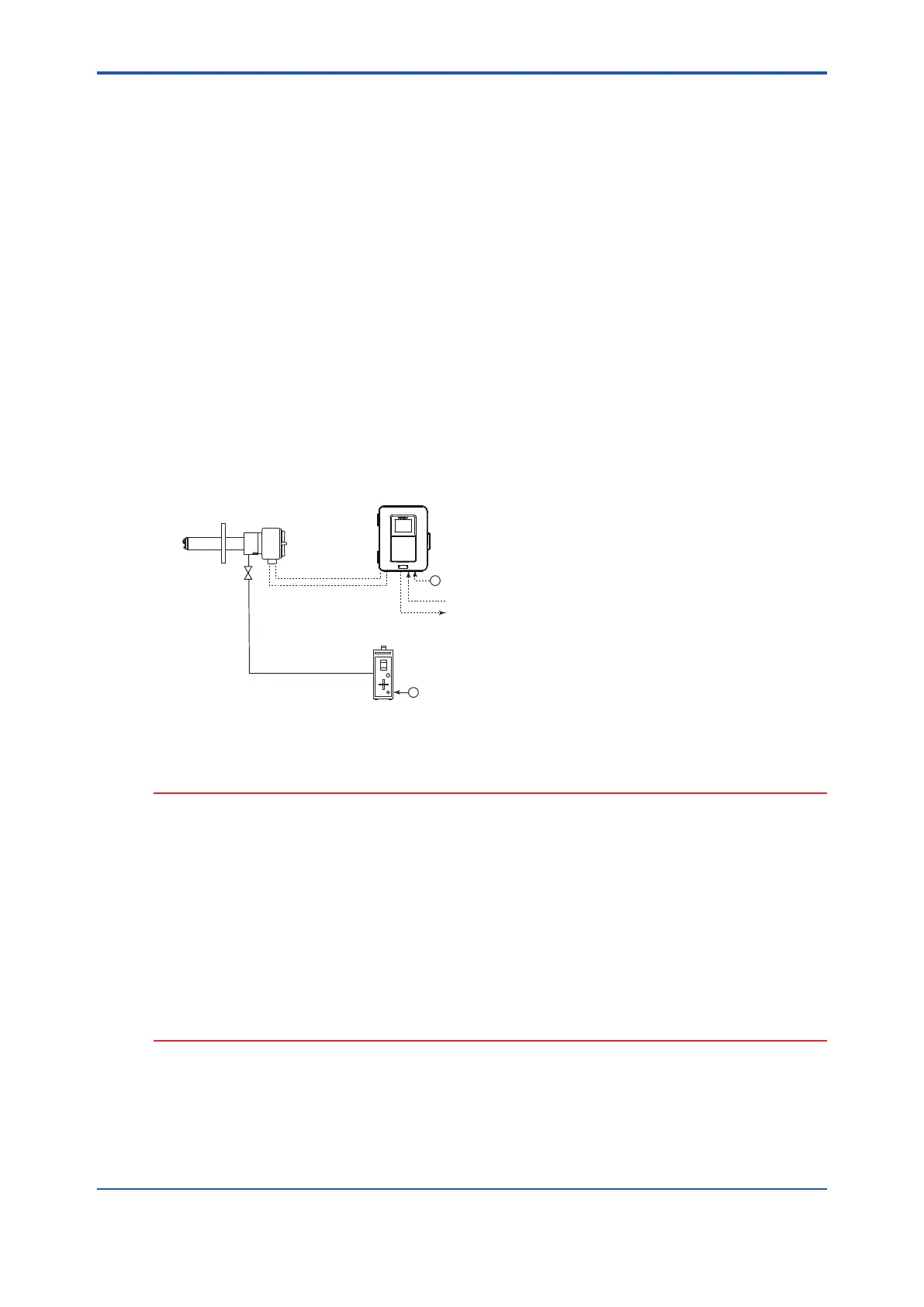
The piping in System 1 is illustrated in Figure 4.1.
~
~
ZO21S Standard gas unit
ZR22G Separate type
Zirconia Oxygen/Humidity Analyzer, Detector
ZR802G Zirconia Oxygen/Humidity Analyzer,
Explosion-proof Converter
Stop valve
Calibration gas
100 to
240 V AC
100/110/115/200/220/240 V AC
Contact input
Analog output, Contact output
Digital output (HART)
Signal
(6-core shield cable)
Heater (2-core)
Figure 4.1 Piping in System 1
CAUTION
• The stop valve should be connected directly to the detector. If any piping is present between
the detector and the stop valve, water may condense in the pipe, which may cause damage
to the detector by rapid cooling when the calibration gas is introduced.
The stop valve should be closed except while the calibration gas is being introduced.
• If a high temperature detector is used (the sample gas temperature is 700°C or higher),
the detector is not clean.
• The reference gas should have an oxygen concentration identical to that of fresh air (21%).
• When a high temperature detector is used, the sample gas is vented into the surrounding
air.
is installed.
Piping in System 1 is as follows:
• Connect a stop valve to the nipple at the calibration gas inlet of the detector. Then mount
a joint for a 6 mm (O.D.) x 4 mm (I.D.) soft tube at the stop valve connection hole of the
inlet side (see Section
“4.1.2 Connection to the Calibration Gas Inlet”). The tube is to
be connected to this joint only during calibration.
 Loading...


