<4. Piping>
4-7
IM 11M12G01-02EN 1sh Edition : Mar. 25, 2021-00
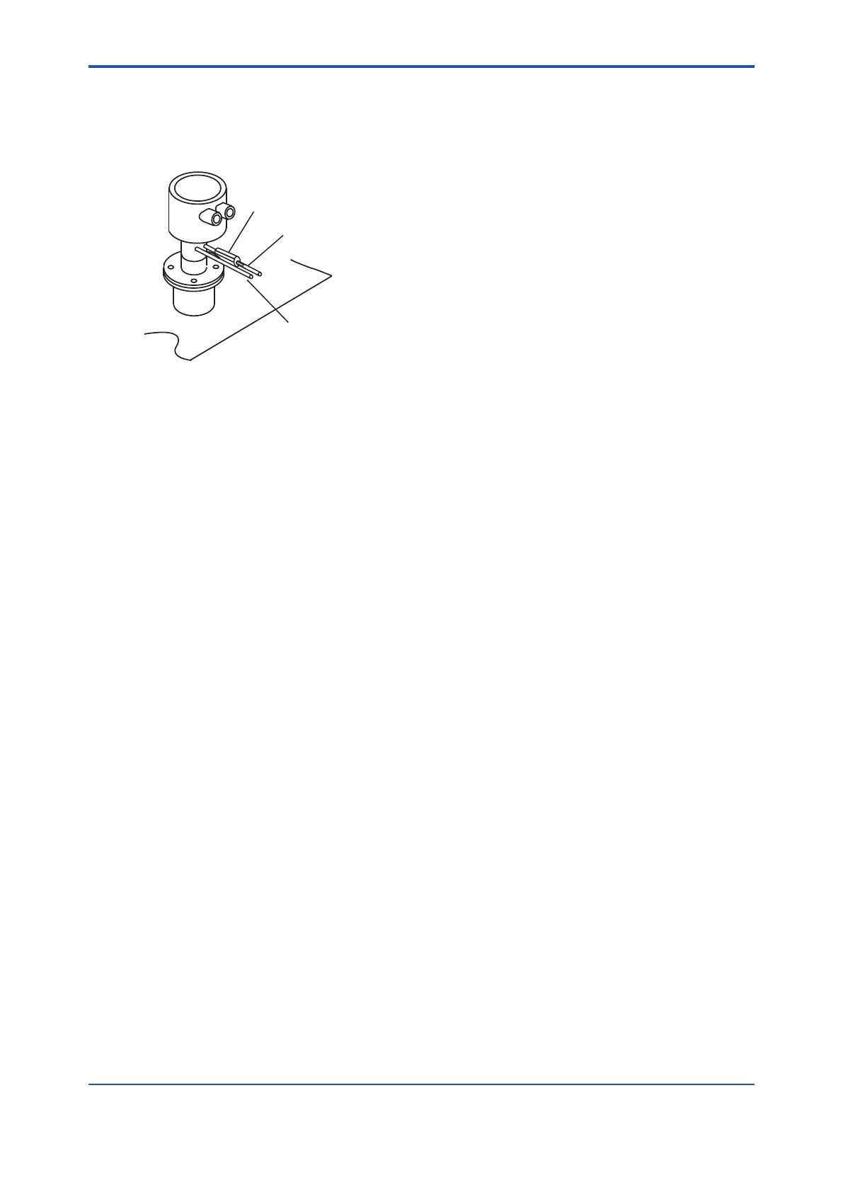
market) at the calibration gas inlet of the detector as illustrated in Figure 4.8.
(The check valve or the stop valve may have been mounted on the detector when shipped.)
larger (I.D.) (or nominal size 1/4 inch).
F4-8E.ai
Stop valve or Check valve
Piping for the calibration gas, 6 mm (O.D.)
by 4 mm (I.D.) Stainless steel pipe
Piping for the reference gas, 6 mm (O.D.)
by 4 mm (I.D.)Stainless steel pipe
Figure 4.8 Piping for the Calibration Gas Inlet
4.2.3 Piping for the Reference Gas
setting unit.
Use a 6 mm (O.D.) x 4 mm or larger (I.D.) (or nominal size 1/4 inch) stainless steel pipe between
4.2.4 Piping to the High Temperature Probe Adapter
Refer to Section “4.1.4 Piping to the High Temperature Probe Adapter”.
4.3 Piping for System 3
however, the piping is basically the same as that of System 2. Refer to Section
“4.2 Piping
for System 2”.
Adjust secondary pressure of both the air set and the zero gas reducing valve so that these
instrument air) are set by a single needle valve.
After installation and wiring, check the calibration contact output (see Sec.
“7.11.2
Checking Calibration Contact Output”), and adjust zero gas reducing valve and calibration gas
When blow back function is used by contact input to the ZR802G converter, install blow back
piping as illustrated in “
n Blow Back Piping”.
Note: Blow back function means the function to get rid of dust inside a probe in a high temperature probe adapter by using compressed
air, when a high temperature detector is used.
It is recommended to use ZH21B dust protector to protect the probe output from dust
agitation (i.e., to prevent combustible materials from entering the probe cell) where humidity
measurements are made under dusty or combustible environment.
 Loading...


