<4. Piping>
4-3
IM 11M12G01-02EN 1sh Edition : Mar. 25, 2021-00
4.1.2 Connection to the Calibration Gas Inlet
When carrying out calibration, connect the piping (6(O.D) ~4(I.D.) mm tube) from the standard
by YOKOGAWA) on a nipple (found on the local market) as illustrated in Figure 4.2, and mount a
joint (also found on the local market) at the stop valve tip. (The stop valve may be mounted on the
detector prior to shipping the detector.)
Note: Mount the stop valve close to the detector.
F4-2E.ai
NippleStop valve
Tube connection joint
Figure 4.2 Connection to the calibration gas inlet
4.1.3 Connection to the Reference Gas Inlet
convection for the reference gas (models ZR22G----C). Leave the plug as it is . If the
air around the detector is polluted and the necessary oxygen concentration (21 vol%O
2
)
cannot be obtained, prepare piping the same as which described in Section 4.2, System 2.
described in Section 4.2, System 2 (models ZR22G----E or P).
4.1.4 Piping to the High Temperature Probe Adapter
• The sample gas should be at a temperature below 700°C before reaching the detector
sensor. If the gas is under negative pressure, it should be fed to the detector by suction.
•
For usage of the probe adapter when using high temperature detector, refer to Section “3.2.1
Usage of the High Temperature Probe Adapter (ZO21P-H)”.
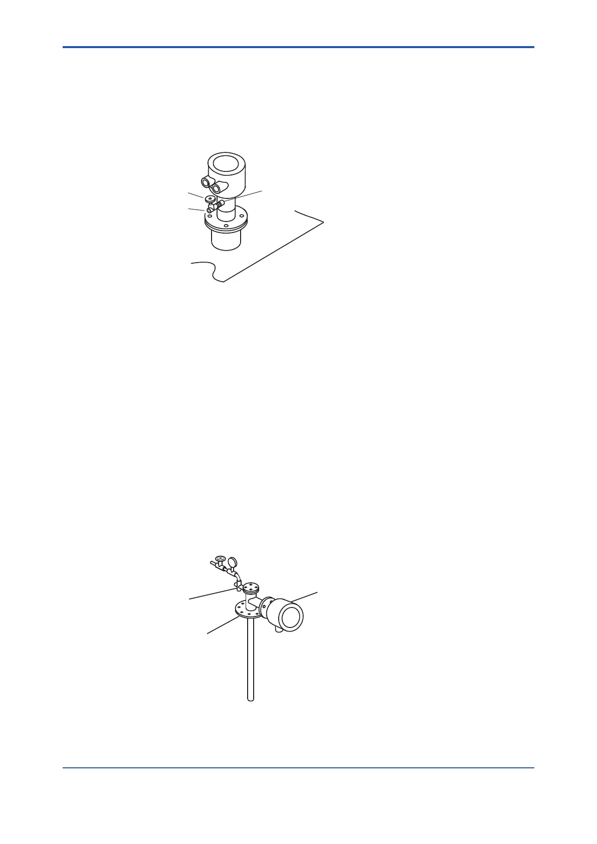
• If the sample gas is under negative pressure, connect the ejector assembly (E7046EC/
E7046EN) as illustrated in Figure 4.3. Mount the pressure gauge as close as possible to
the ejector assembly. However, if the ambient temperature is too high, mount the gauge in a
location with a temperature below 40°C.
Ejector assembly for
high temperature use
Adapter for
high temperature probe
Detector
F4-3E.ai
Figure 4.3 Mounting the ejector assembly
kPa, the sample gas temperature may not be below 700°C at the detector.
 Loading...


