<5. Wiring>
5-12
IM 11M12G01-02EN 1sh Edition : Mar. 25, 2021-00
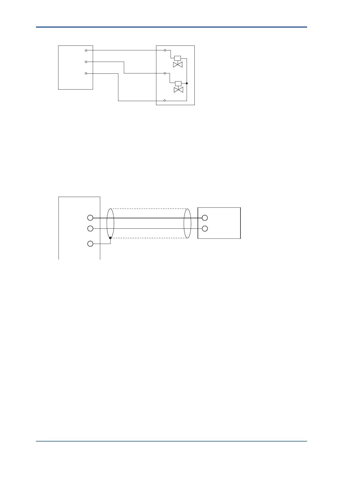
ZR802G
Converter
ZR40H Automatic
Calibration Unit
AC-ZERO
AC-COM
AC-SPAN
Zero
Span
Figure 5.14 Wiring for Automatic Calibration Unit
5.2.10 Pressure or Temperature Input Wiring
(Only for Humidity Analyzer)
connect a two-wire pressure or temperature transmitter (hereinafter referred to as transmitter).
connected transmitter, in the case where the setting is “Pressure or Temperature input selected”
and “external input”. As for the wiring of the temperature transmitter and thermocouples, refer to
appropriate temperature transmitter instruction manual.
AI(+)
AI(-)
FG
Shielded cables
+
-
Converter
Pressure Temperature
transmitter
F5-14E.ai
Figure 5.15 Pressure or temperature input wiring
l Applicable Temperature Transmitter
Apply a transmitter that is suit for the following interfaces:
Output signal: 4 to 20 mA DC, two-wire system (*1)
Maximum supply voltage from the analyzer: 25.2 V DC
Input resistance of the analyzer: Maximum 250 V (The load resistance of the transmitter is the
total of wiring resistance and input resistance.)
Temperature Transmitter Burnout
When outputting a burnout signal of the temperature transmitter with a contact output of the
analyzer, use “high/low-limit pressure (temperature) alarm”. (Refer to Section 8.4, “Contact
Output Setting.”) In this case, set the burnout signal of the transmitter to exceed the high limit (20
mA or more).
Cable Specications
Use a two-core shielded cable for wiring.
Wiring Procedure
appropriate crimp contacts. Ensure that the cable shield be connected to the FG terminal of
the converter.
(2) Be sure to connect “+” and “-” polarities correctly.
 Loading...


