<11. Inspection and Maintenance>
11-4
IM 11M12G01-02EN 1sh Edition : Mar. 25, 2021-00
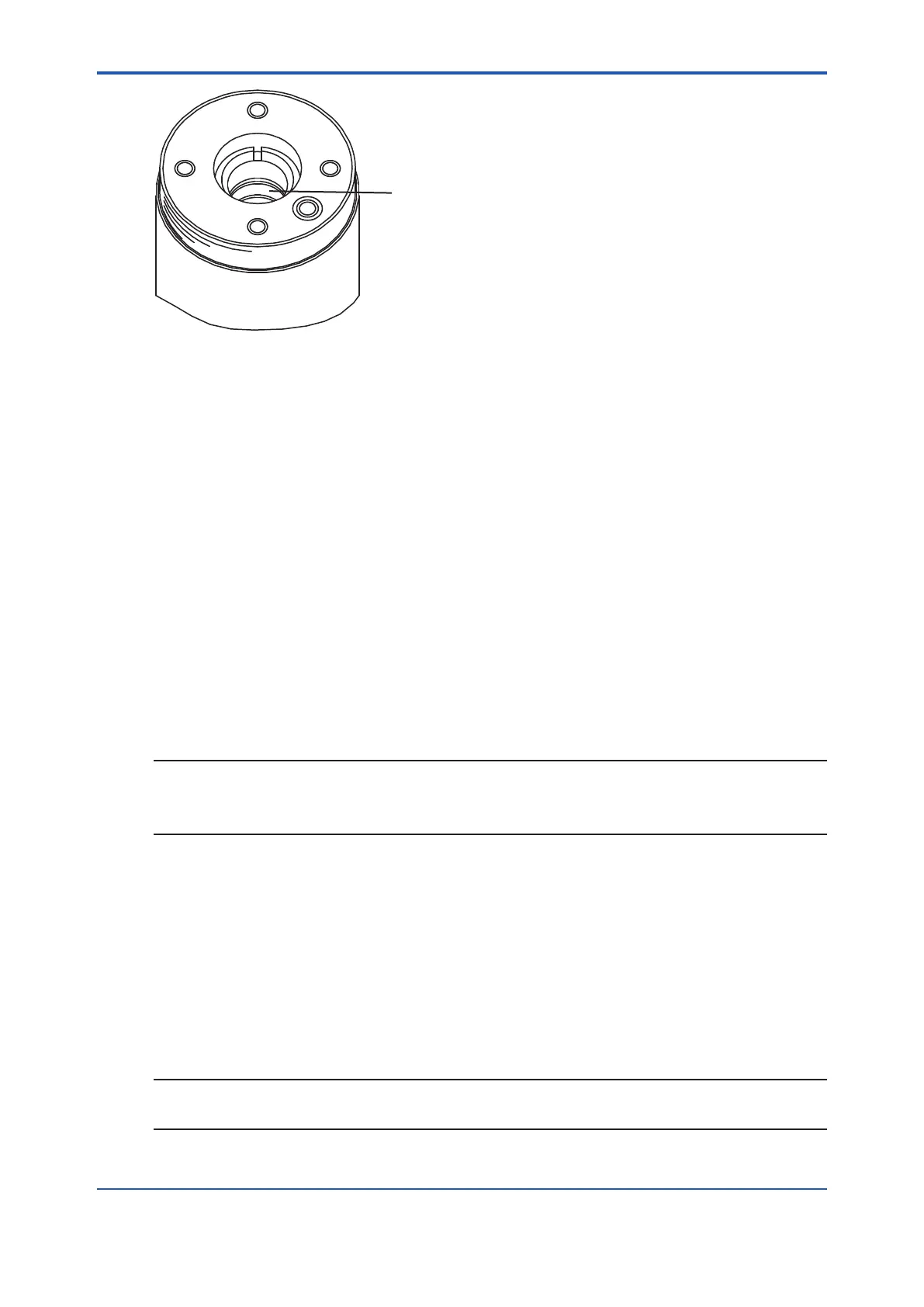
Groove in which the contact
(E7042BS) is placed
F11.2E.ai
Figure 11.3 Installing the Contact
Install the metal O-ring in that O-ring groove, and then insert the sensor in the probe while
turning it clockwise. After inserting it until the metal O-ring comes in contact with the probe’s
O-ring contact surface, properly align the U-shaped pipe insertion holes with the bolt
openings.
support into the probe.
(4) Coat the threads of the four bolts with anti-seize grease and then screw them in along with
perfectly horizontal to the O-ring’s working face in the probe.
one of the other bolts followed by its opposing bolt, each also 1/8 turn. This continues
approximately 5.9 N • m. If they are not uniformly tightened, the sensor or heater may be
damaged.
Replacement of the sensor assembly is now complete. Install the detector and restart
operation. Calibrate the instrument before making a measurement.
NOTE
bolts are being tightened, abnormal strain or bolt breakage may result.
So, tighten the bolts following the instructions given above.
11.1.4 Replacement of the Heater Unit
This section describes the replacement procedure for the heater unit.
The sensor or ceramic heater-furnace core internal structure is subject to fracturing, so do NOT
subject it to strong vibrations or shock. Additionally, the heater unit reaches high temperatures
and is subjected to high voltages. So, maintenance services should be performed after the power
For details, refer to IM11M12A01-21E “Heater Assembly“.
NOTE
If the heater strut assembly can not be removed because a screw has fused to its thread, one of
 Loading...


