<4. Piping>
4-11
IM 11M12G01-02EN 1sh Edition : Mar. 25, 2021-00
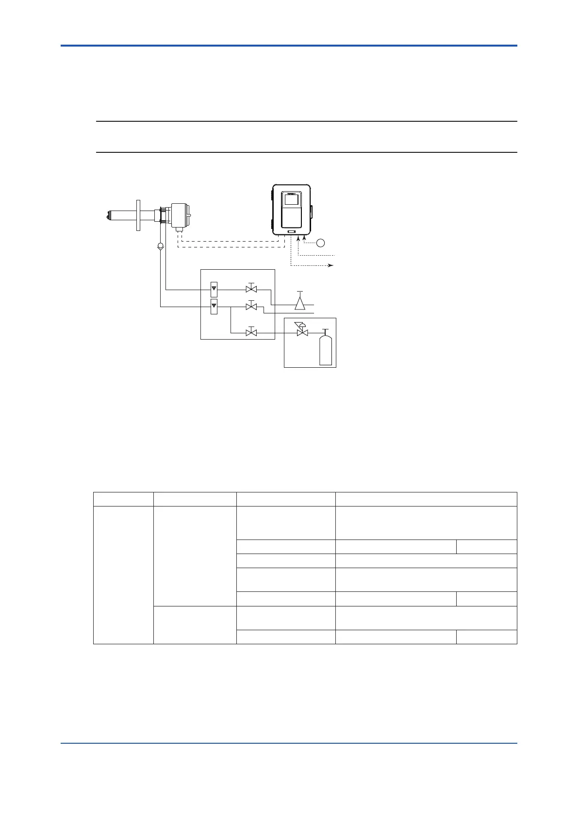
Figure 4.14 illustrates an example of System 2 using a detector with pressure compensation.
NOTE
When using the ZA8F Flow Setting Unit and ZR40H Automatic Calibration Unit, please note that
~
ZA8F Flow Setting Unit
ZR22G Separate type
Zirconia Oxygen Analyzer, Detector
ZR802G Converter
Reference
gas
Calibration
gas
Stop valve
or
Check valve
Needle
valve
Flowmeter
Instrument air
Air Set
Pressure
reducing
valve
Zero gas cylinder
Calibration gas
unit case
Span gas
(Same as Zero gas calibration unit)
100 to
240 V AC
Contact input
Analog output, Contact output
Digital output (HART)
Signal
(6-core shield cable)
Heater (2 core cable)
Figure 4.14 System 2 using a detector with pressure compensation
4.4.1 Piping Parts for a System using Detector with
Pressure Compensation
Check that the parts listed in Table 4.3 are ready.
Table 4.3 Piping Parts
Detector Piping location Parts Name Note
Detector with
pressure
compensation
Calibration gas inlet Stop valve or check
valve
Recommended by YOKOGAWA (L9852CB
or G7016XH) Provided by YOKOGAWA
(K9292DN or K9292DS)
Nipple * Rc 1/4 or 1/4 NPT General parts
Zero gas cylinder User´s scope
Pressure reducing valve Recommended by YOKOGAWA
(G7013XF or G7014XF)
Joint for tube connection Rc 1/4 or 1/4 NPT General parts
Reference gas inlet Air set Recommended by YOKOGAWA
(G7003XF/K9473XK or G7004XF/K9473XG)
Joint for tube connection Rc 1/4 or 1/4 NPT General parts
General parts can be found on the local market.
4.4.2 Piping for the Calibration Gas
Calibration gas piping is basically identical to that of System 2. See Section “4.2.2 Piping
for the Calibration Gas”.
 Loading...


