<5. Wiring>
5-5
IM 11M12G01-02EN 1sh Edition : Mar. 25, 2021-00
5.2 Wiring
5.2.1 Connection to Converter
To connect the wiring to the converter, proceed as follows:
(1) M4 screws are used for the terminals of the converter. Each cable should be terminated in
the corresponding size crimp-on terminals.
(2) When a rubber insulated glass braided wire is used for wiring to the detector, use a terminal
box. For wiring between the terminal box and the converter, basically use a cable that
withstand temperatures of at least 80°C.
NOTE
The above is to prevent moisture or corrosive gas from entering the converter.
Where the ambient environment of the detector and the converter is well-maintained, it is
permissible to connect the wiring from the detector directly to the converter with protection by
conduits.
WARNING
This wiring is to carry power for the heater. Be careful to wire the correct terminals, and be
careful not to ground or short circuit terminals when wiring, as otherwise the instrument may be
damaged.
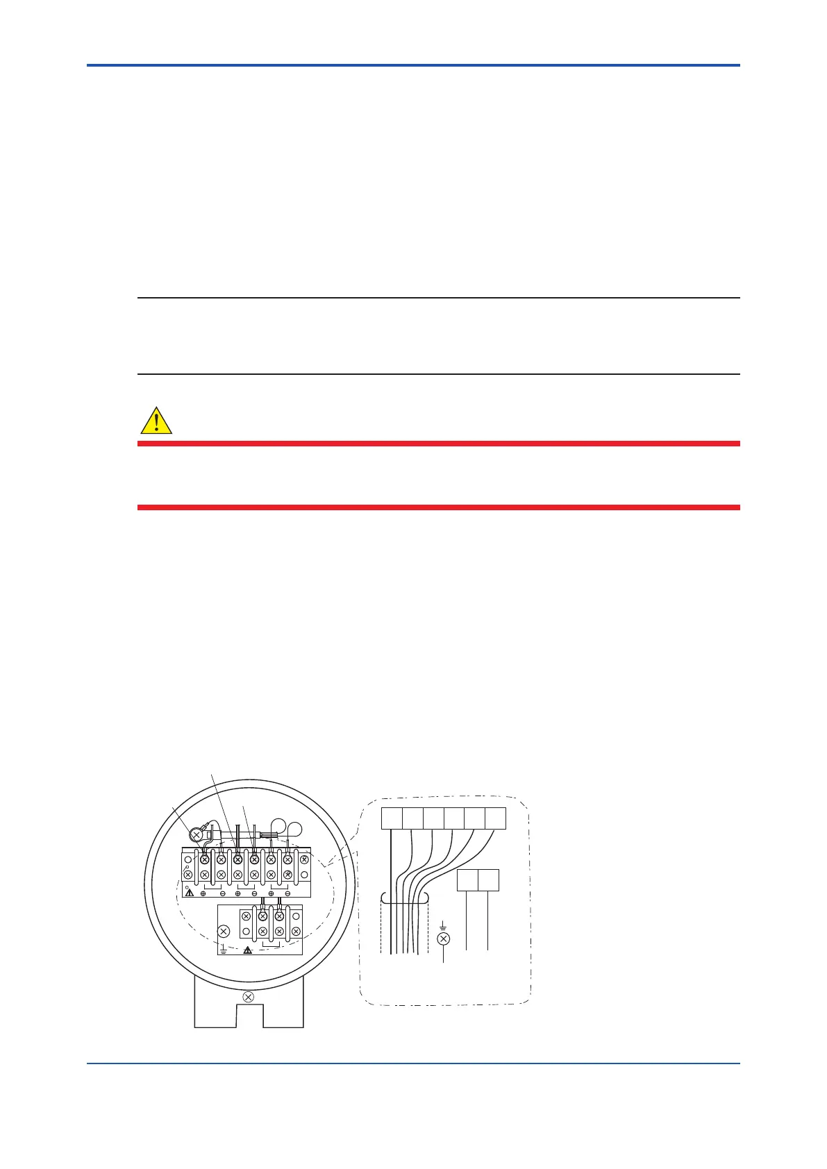
5.2.2 Connection to Detector
When connecting the cable to the detector, proceed as follows:
detector.
The detector may need to be removed in future for maintenance, so be sure to allow
(2) If the ambient temperature at the location of wire installation is 75 to 150°C, be sure to use a
braided wire” is used, keep the wire away from noise sources to avoid noise interference.
(3) The size of the terminal screw threads is M3.5. Each cable should be terminated in the
corresponding size crimp-on terminals contact (*1) respectively.
CELL +
TC +
TC -
TCCELL CJ
1 2 3 4 5 6
87
H
T
R
CELL
(+)
CELL
(-)
TC
(+)
TC
(-)
CJ
(+)
CJ
(-)
HTR HTR
To converter,
or
terminal box
To ground
To converter,
or
terminal box
Figure 5.4 Terminal assignment of detector
 Loading...


