<5. Wiring>
5-4
IM 11M12G01-02EN 1sh Edition : Mar. 25, 2021-00
1
FG
2
AO1
(+)
36
FG
37
GND
38
B-
39
A+
40
Termination
41
Termination
3
AO1
(-)
Ether
Ethernet RS485
4
AO2
(+)
5
AO2
(-)
6
CJ
(+)
7
CJ
(-)
8
TC
(+)
9
TC
(-)
10
CELL
(+)
11
CELL
(-)
12
FG
13
DI-1
14
DI-2
15
DI-C
16
AI
(+)
17
AI
(-)
18
AC-
ZERO
19
AC-
SPAN
20
AC-
COM
21
FG
22
FG
CELL
(+)
RS-485
CELL
(-)
TC
(+)
TC
(-)
CJ
(+)
CJ
(-)
23
DO-1
24
DO-1
25
DO-2
26
DO-2
27
DO-3
28
DO-3
29
DO-4
30
DO-4
31
HTR
32
HTR
33
L
34
N
35
G
HTR HTR
100~240 V AC
50/60 Hz
*1
*1
*1
*2
*3 *4
Contact
output 1
Contact
output 2
Contact
output 3
Contact
output 4
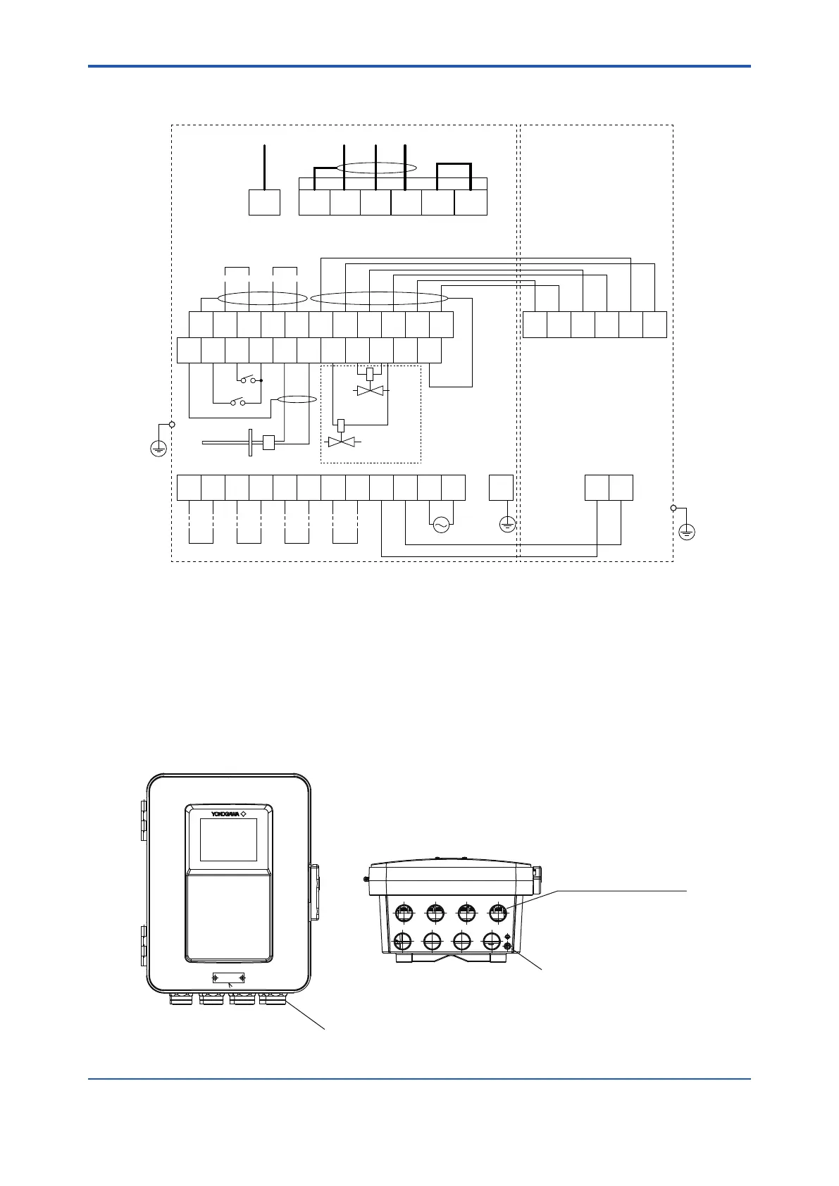
*1: The ground wiring of the converter should be connected to either the protective ground terminal in the equipment or the
ground terminal of the converter case.
Ground to earth, ground resistance: 100 Ω or less.
*2: Option (Temperature or Pressure transmitter provide by user) for humidity measurement.
*3: Suffix Code “-E”
*4: Suffix Code “-M”
Contact input 1
Contact input 2
Solenoid valve for
automatic calibration
Span gas
Zero gas
Solenoid valve for zero gas
for automatic calibration
ZR802G
Zirconia Oxygen/Humidity Analyzer
ZR22G
Zirconia Oxygen/Humidity Analyzer,
Detector
Analog
output 1
4–20 mA DC
Digital output
(HART)
Analog
output 2
4–20 mA DC
Figure 5.2 Wiring connection to the converter
5.1.3 Mounting of Cable Gland
For each cable connection opening of the converter, mount a conduit that matches the thread
size, or a cable gland.
8 - G1/2, *8 - 1/2 NPT etc
(wiring connection) (Female)
*: 1/2 NPT with plug
cable gland
earth terminal (M4)
Figure 5.3 Cable gland mounting
 Loading...


