<5. Wiring>
5-10
IM 11M12G01-02EN 1sh Edition : Mar. 25, 2021-00
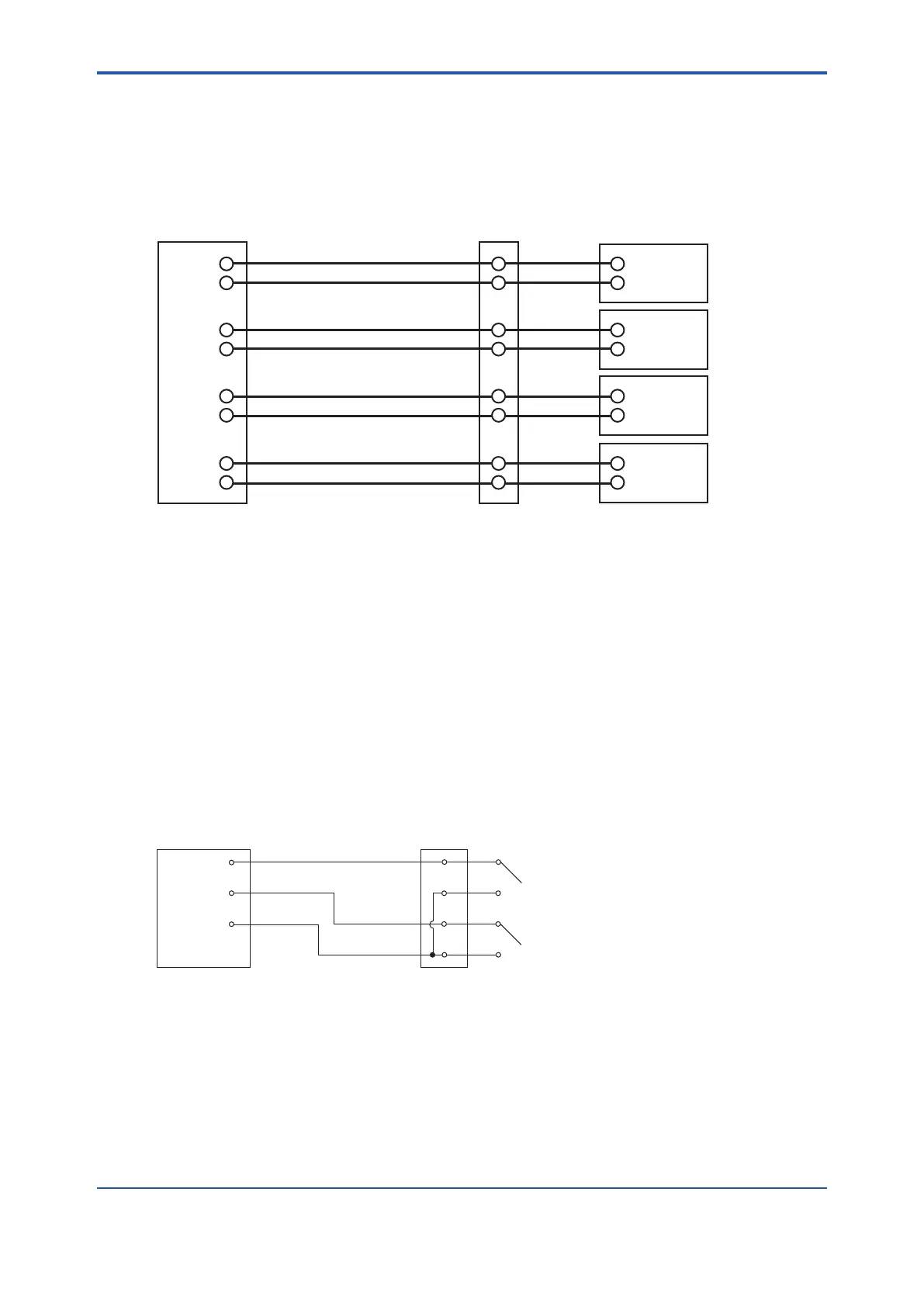
5.2.7 Contact Output Wiring
Contact outputs 1 to 3 can be freely assigned to “low limit alarm”, “high limit alarm”, etc. user
closed on error output) also cannot be changed.
When using these contact outputs, install the wiring as follows:
#1 Output
#2 Output
#3 Output
#4 Output
DO-1
DO-1
DO-2
DO-2
DO-3
DO-3
Terminal box Annunciator or the like
ZR802G
Converter
DO-4
DO-4
Figure 5.11 Contact output wiring
Cable Specications
Number of wire in cable varies depending on the number of contact used.
Wiring Procedure
(1) M4 screws are used for the terminals of the converter. Each cable should be terminated
corresponding to crimp-on terminals.
(2) The capacities of the contact output relay are 30 V DC 3 A, 250 V AC 3 A. Connect a load
(e.g. pilot lamp and annunciator) within these limits. AC and DC voltage cannot be mixed.
5.2.8 Contact Input Wiring
To use these contact signals, wire as follows:
ZR802G
Converter
Terminal box
DI-1
DI-C
DI-2
Contact input 1
Contact input 2
Figure 5.12 Contact Input Wiring
Cable Specications
Use 2-core or 3-core cable for this wiring. Depending on the number of input(s), determine which
cable to use.
Wiring Procedure
(1) M4 screws are used for the terminals of the converter. Each cable should be terminated
corresponding to crimp-on terminals.
 Loading...


