COPYRIGHT
©
2000 CANON INC. 2000 2000 2000 2000 CANON iR5000/iR6000 REV.0 JULY 2000
CHAPTER 4 IMAGE FORMATION SYSTEM
4-53 P
Protect the removed photosensi-
tive drum against dirt and
scratches with five to six sheets
of copy paper or with the drum
protective sheet stored near the
waste toner case.
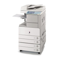
3) Remove it from the rear together with
the drum heater control PCB [3].
4) Disconnect the connector [4], and de-
tach the drum heater [5] from the photo-
sensitive drum.
F04-702-05
7.2.3 Mounting the Photosensitive Drum
Mount the photosensitive drum by reversing the steps used to remove it; however, be sure
not to soil or scratche the drum and not to trap the cable of the drum heater.
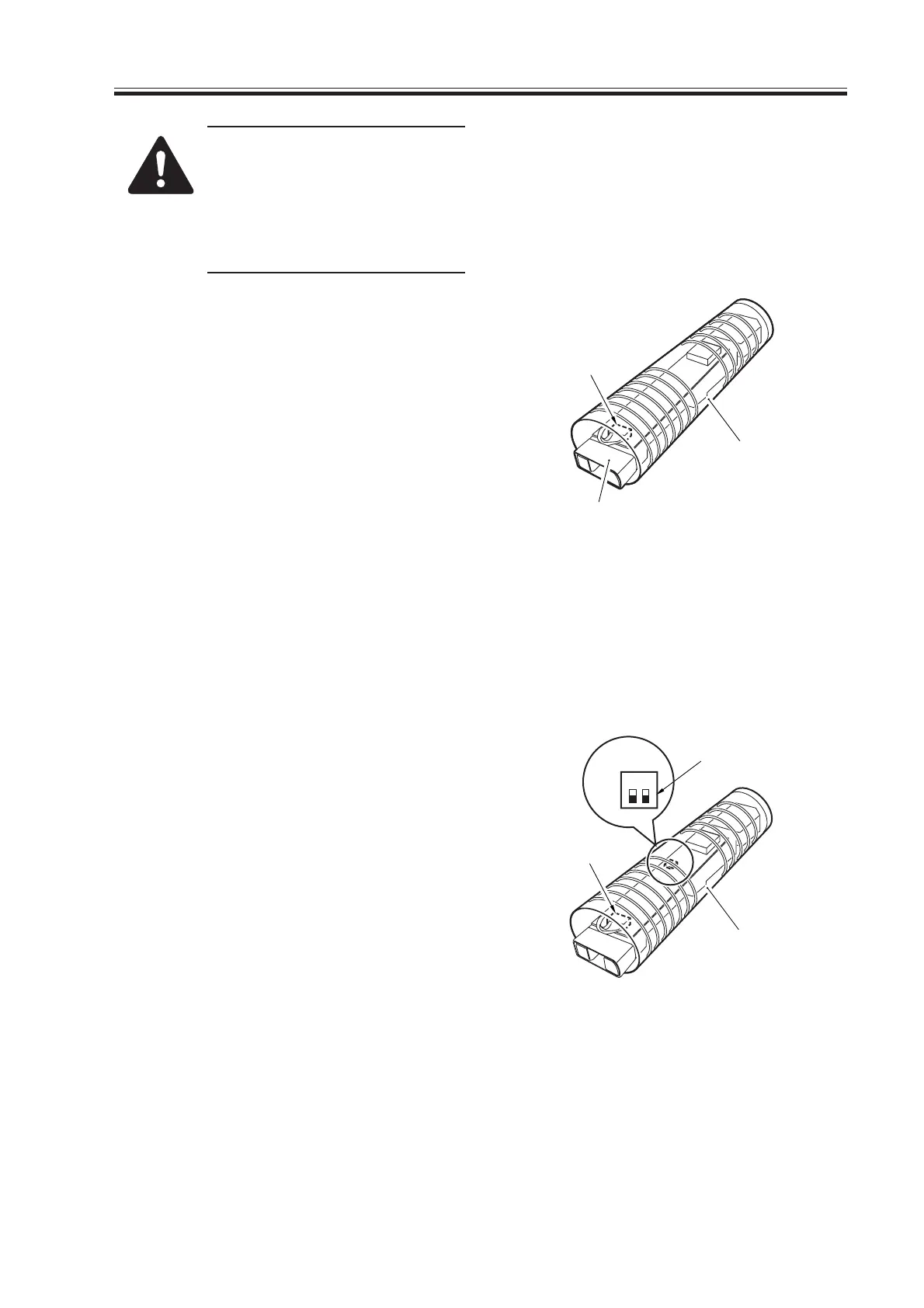
7.2.4 Setting the DIP Switch for the Drum Heater Control PCB
1) Remove the drum heater assembly. (See
p. 4-52P.)
2) Disconnect the connector [1], and de-
tach the drum heater assembly [2].
3) Set the DIP switch (SW2001-1) [3] on
the drum heater control PCB.
F04-702-06
[3]
[5]
[4]
[2]
[1]
[3]
12
SW2001
ON
Download Free Service Manual at http://printer1.blogspot.com

 Loading...