COPYRIGHT
©
2000 CANON INC. 2000 2000 2000 2000 CANON iR5000/iR6000 REV.0 JULY 2000
CHAPTER 6 FIXING SYSTEM
6-6 P
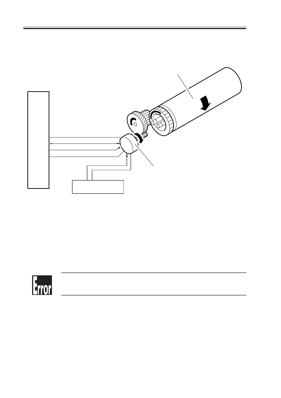
The system makes use of the following signals:
[1] Fixing motor drive signal; when ‘1’, the motor turns on.
[2] Fixing motor drive lock signal; when the speed of rotation of the fixing motor reaches
a specific level, ‘0’.
F06-202-01
E014 (fixing motor speed error)
It is indicated when the drive lock signal is absent for 2 sec or more 2 sec
after the fixing motor drive signal (M19ON) is generated.
DC controller PCB
M19LD [2]
GND
5V
M19ON [1]
M19
Fixing upper roller
Fixing motor
J106
-A15
-A16
-A17
-A18
24V
DC power supply PCB
GND
J4005-1
-2
2.2 Controlling the Drive of the Fixing Roller
The system used to control the fixing roller is constructed as follows:
Download Free Service Manual at http://printer1.blogspot.com

 Loading...