COPYRIGHT
©
2000 CANON INC. 2000 2000 2000 2000 CANON iR5000/iR6000 REV.0 JULY 2000
CHAPTER 3 STANDARDS AND ADJUSTMENTS
3-32 T
11) Connect the connector of the cable (of the potential control PCB).
12) Mount the front switch cover, and close the front cover.
13) Mount the rear upper cover.
14) Turn on the main power switch.
8.3.2 Method 2
1) Disable potential control so that the machine will be in non-auto control mode.
2) Turn off the main power switch.
3) Remove the potential sensor from the machine.
4) Connect the connector of the potential controller to the connector on the machine side.
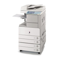
5) Fit the electrode (FY9-3012) [2] designed for checking potential sensors to the potential
sensor [1].
F03-803-04
When fitting the electrode to the potential sensor, be sure to keep the mag-
net of the electrode away from the potential sensor cover.
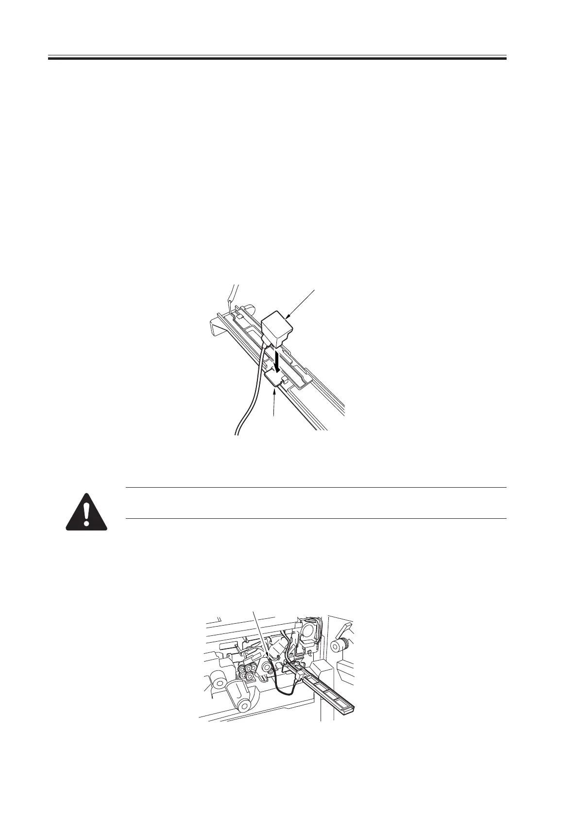
6) Connect the clip [3] designed for making checks to the frame of the machine frame
(GND).
F03-803-05
[2]
[1]
[3]
Download Free Service Manual at http://printer1.blogspot.com

 Loading...