COPYRIGHT
©
2000 CANON INC. 2000 2000 2000 2000 CANON iR5000/iR6000 REV.0 JULY 2000
CHAPTER 7 EXTERNALS AND CONTROLS
7-21 P
5.4 PCBs
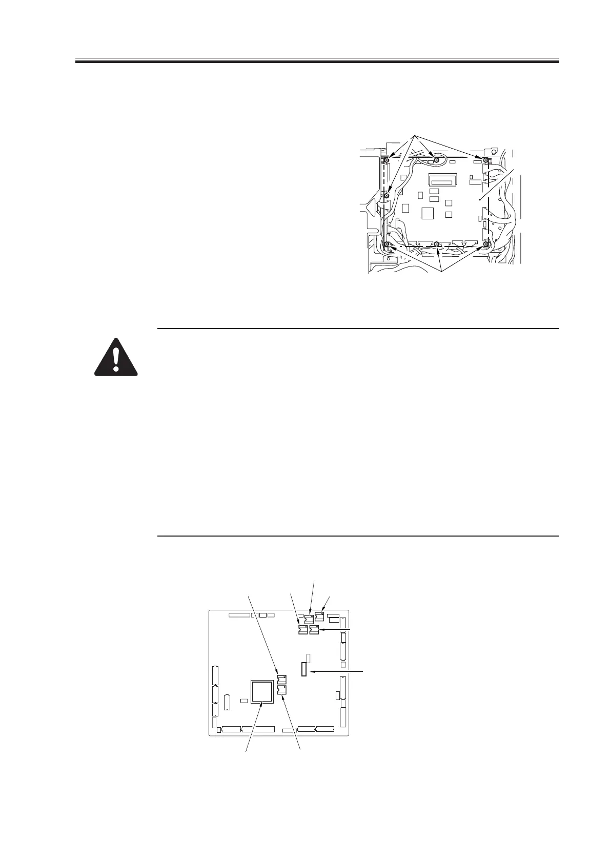
5.4.1 DC Controller PCB
1) Remove the rear upper cover.
2) Disconnect the 26 connectors, and re-
move the seven screws [1]; then, detach
the DC controller PCB [2].
F07-504-01
Keep the following three points in mind when replacing the PCBs:
• Be sure to transfer the six EEP-ROMs from the old to new PCBs; at
that time, be sure to refer to the color of each round label attached to the
EEP-ROM for correct transfer.
• Be sure to enter the values indicated on the label [3] on the new PCB in
service mode by making the following selections:
COPIER>ADJUST>HV-TR>D-PRE-TR
COPIER>ADJUST>HV-TR>D-HV-TR
COPIER>ADJUST>HV-SP>D-HV-SP
COPIER>ADJUST>DEVELOP>D-HV-DE
• Be sure to transfer the shorting connector [4] of J303 on the PCB from
the old to new PCB. (Keep in mind that failure to do so will disable the
control panel indication.)
F07-504-02
[1]
[1]
[2]
Red (IC105)
Brown
(IC104)
Yellow
(IC109)
Blue
(IC127)
White (IC130)
Green (IC110)
J303
[3]
[4]
Download Free Service Manual at http://printer1.blogspot.com

 Loading...