COPYRIGHT
©
2000 CANON INC. 2000 2000 2000 2000 CANON iR5000/iR6000 REV.0 JULY 2000
CHAPTER 4 IMAGE FORMATION SYSTEM
4-57 P
7.4 Potential Sensor/Potential Control PCB
7.4.1 Removing the Potential Sensor/Potential Control PCB
Be sure to replace the potential
sensor and the potential control
PCB at the same time.
1) Open the front cover, and slide out the
hopper unit.
2) Remove the developing assembly and
the primary cooling fan.
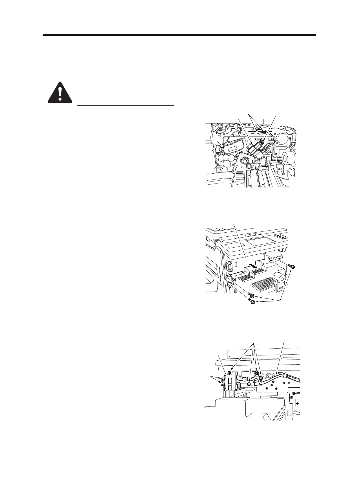
3) Disconnect the connector [1], and re-
move the screw [2]; then, detach the po-
tential sensor assembly [3].
F04-704-01
4) Remove the three screws [4], and detach
the front door switch cover [5].
F04-704-02
5) Free the cable [6] from the cable guide.
6) Remove the six screws [7], and detach
the door switch assembly [8].
F04-704-03
[1]
[2]
[3]
[4]
[5]
[8]
[7]
[7]
[6]
Download Free Service Manual at http://printer1.blogspot.com

 Loading...