COPYRIGHT
©
2000 CANON INC. 2000 2000 2000 2000 CANON iR5000/iR6000 REV.0 JULY 2000
CHAPTER 3 INSTALLATION
3-6 S
Checks/remarks
Check to make sure that none is
missing.
Step
5
6
7
8
Work
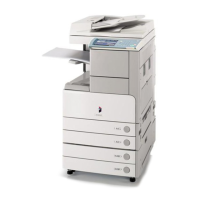
Holding the two grips (front, rear) on the
side of the pickup assembly, lift the machine
slightly to remove the pad.
Turn over the slope plates; then match the
pin holes in the skids with those in the slope
plates, and fit the pins (one each).
Holding the grips (front, rear) found on the
machine, move the machine off the skid by
sliding it on the slope plates.
Remove the packaging tape from the body.
Open the cardboard box that comes with the
machine, and take out the parts and compo-
nent members.
2.4 Mounting the Scanner
Step
1
2
Work
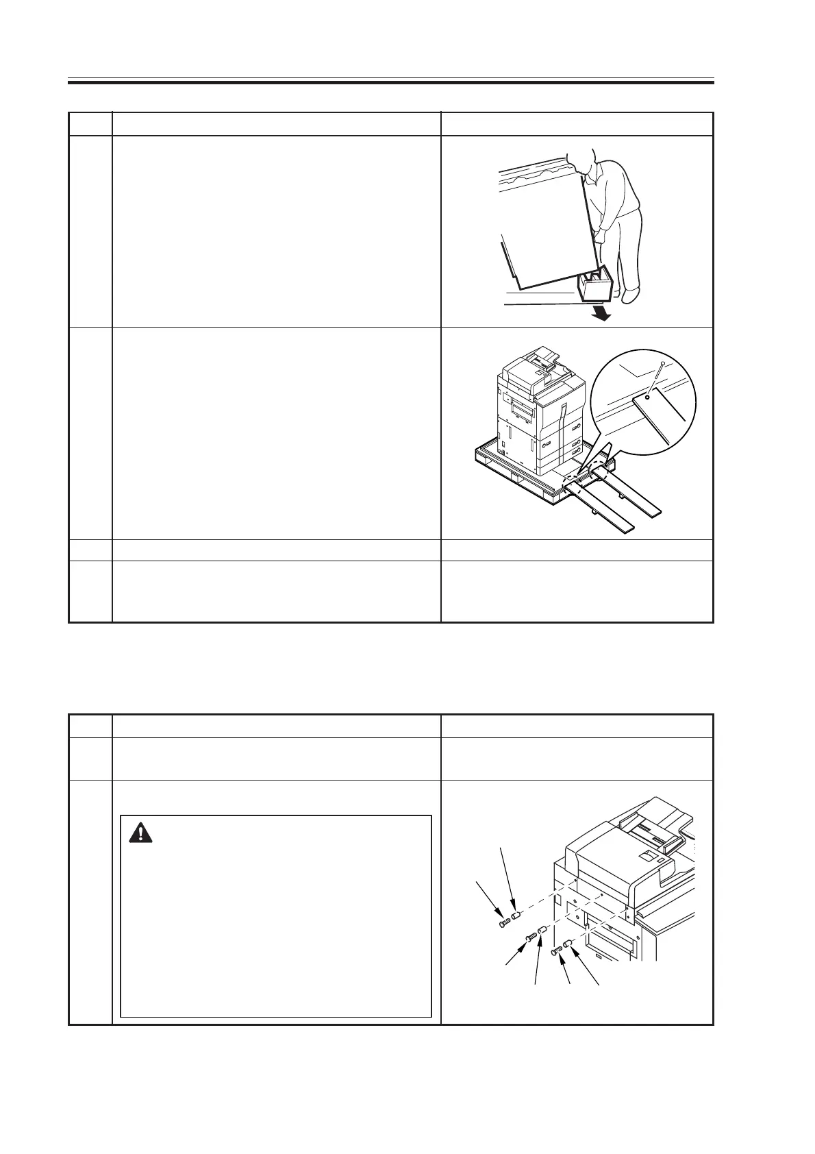
Open the ADF, and remove the packing ma-
terial.
Remove the scanner fixing screw and spacer.
1.Take care not to let the spacer fall
inside the machine.
2.Store away the fixings for use
when securing the scanner for
possible relocation of the ma-
chine.
3.The middle spacer is longer than
the spacers on both ends; pay at-
tention when using them.
Spacer (short)
Screw
Screw
Screw
Spacer (long)
Spacer (short)
Checks/remarks
Download Free Service Manual at http://printer1.blogspot.com

 Loading...