COPYRIGHT
©
2000 CANON INC. 2000 2000 2000 2000 CANON iR5000/iR6000 REV.0 JULY 2000
CHAPTER 5 PICK-UP/FEEDING SYSTEM
5-40 P
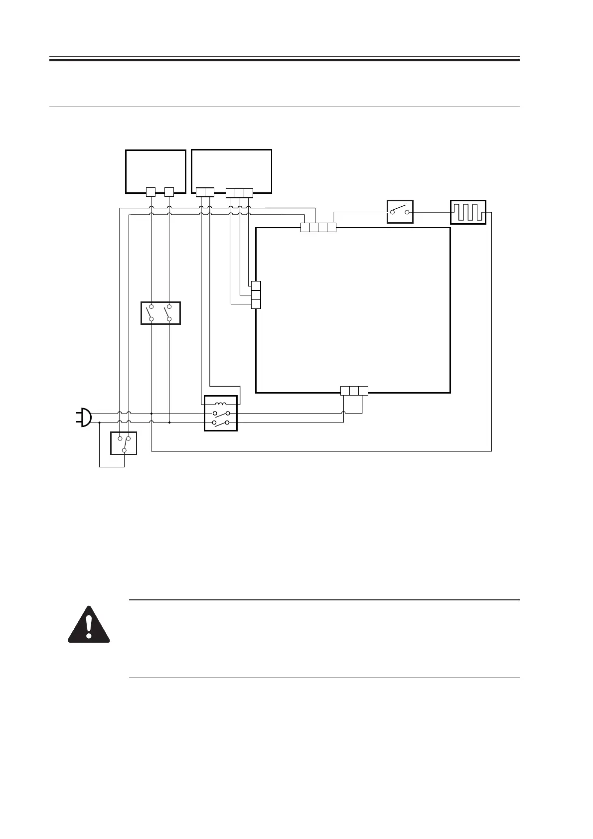
7. Controlling the Cassette Heater
The system used to control the cassette heater is constructed as follow:
F05-700-01
The following signal has the function indicated:
[1] Cassette Heater Drive Control Signal:
When '1', supplies the AC driver PCB with AC power.
The cassette heater switch (SW4) serves to supply power to the heater
through the AC line or to deprive it of power.
If the environment switch (SW3) is off, the heater will not be supplied with
power through the AC line even if the cassette heater switch (SW4) remains
on.
H4
RL1
AC driver PCB
Cassette heater
SW1
Main
power
switch
SW3
Environment switch
DC power
supply PCB
2 1
J4001
DC controller
PCB
43
J119
1
2
8
127 14
1
Power supply
43
J102B
0V
12V
CASSETTE_HEATER_ON [1]
J2052
J2051
J2053
2 1
3 2
SW4
Cassette
heater switch
Download Free Service Manual at http://printer1.blogspot.com

 Loading...