circuits:
o Main expansion base circuit (+/- 5 volts, +/- 12 volts)
o VBatt1 circuits (10 to 18.5 volts)
o VBatt2 circuits (10 to 18.5 volts)
The outputs to the above circuits are located on an edge card connector in
the power supply. The vertical circuit board plugs into this edge card
connector to distribute power to the unit.
Refer to Appendix A for pin assignments for the power supply output
connector.
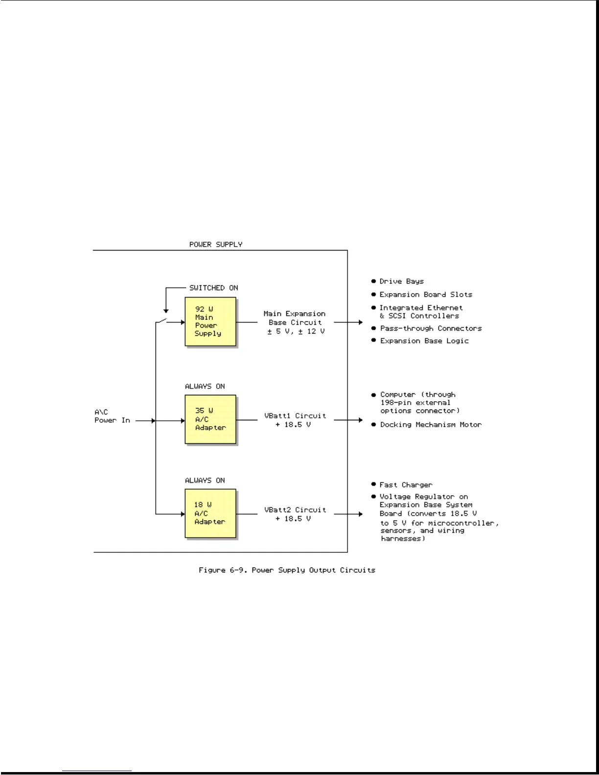
Figure 6-9 illustrates the function of the power supply output circuits.
Main Expansion Base Circuit
The main expansion base circuit provides +/- 5 volts and +/- 12 volts to
the following:
o Internal drive bays
o Expansion board slots
o Integrated Ethernet and SCSI-2 circuitry
o All pass-through connectors
 Loading...