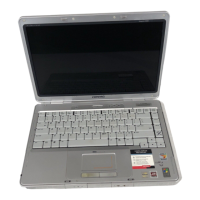
The following list outlines the removal and replacement procedures that are
covered in this chapter:
9.4 Preparation procedures for removal and replacement
9.5 Battery pack
9.6 Bottom cover
9.7 Keylock assembly
9.8 Expansion boards
9.9 Expansion board cage
9.10 Vertical circuit board
9.11 Power supply and bezel
9.12 Docking mechanism
9.13 System board and battery charging compartment
9.14 Battery contacts board
9.15 Drives
- Drive cables
9.16 Drive cages
9.17 Cable harnesses and PCMCIA sensor
9.18 Power and eject switch components
9.19 Horizontal guides and springs
9.20 Top cover
9.4 Preparation Procedures For Removal And Replacement
Before beginning removal and replacement procedures, complete the following
steps:
1. Read and observe the precautions in Section 9.1.
2. Undock the computer if it is docked in the expansion base (refer to
Appendix D).
3. Remove the battery pack from the battery charger in the expansion base,
if one is installed (Section 9.5).
4. Turn off the expansion base.
5. Disconnect the power cord from the electrical outlet.
>>>>>>>>>>>>>>>>>>>>>>>>>>>>>>>>> WARNING <<<<<<<<<<<<<<<<<<<<<<<<<<<<<<<<<
To avoid the risk of electric shock or damage to the expansion base, ensure
that the power cord is disconnected before removing and replacing internal
parts.
>>>>>>>>>>>>>>>>>>>>>>>>>>>>>>>>>>>>><<<<<<<<<<<<<<<<<<<<<<<<<<<<<<<<<<<<<<
6. Turn off all external devices, then disconnect them from the expansion
base.
7. If a monitor is being used, remove it, then remove the monitor stand.
9.5 Batter
Pack
 Loading...
