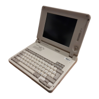
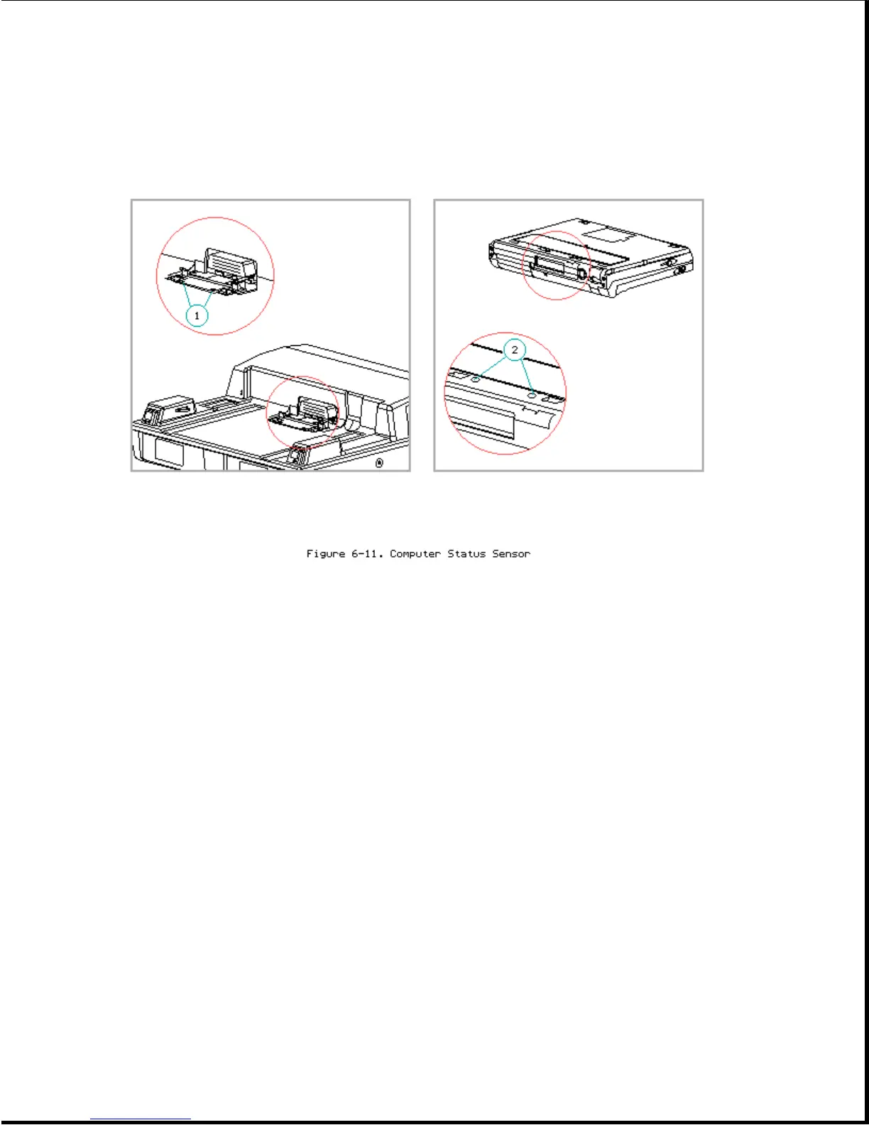
The expansion base has a two-part computer status sensor [1] (Figure 6-11)
on the docking mechanism sled. This sensor corresponds to two sense pads on
the bottom of the Compaq LTE Elite [2] or the bottom of a SmartStation
Adapter when connected to a Compaq LTE Lite. The computer status
sensor/sense pad combination indicates whether the computer is on, off, or
in Standby. The expansion base uses this information to determine if the
computer should be allowed to dock/undock. Refer to Appendix D for more
information on docking and undocking.
The computer status sensor is integrated into the docking mechanism. To
replace the computer status sensor, the docking mechanism must be replaced.
Vertical Circuit Board
The following connectors and switches are on the vertical circuit board
(Figure 6-12):
1. Drive power cable connector
2. IDE hard drive signal cable connector
3. Tape/diskette drive signal cable connector
4, 5. Two full-sized ISA expansion board slots
 Loading...