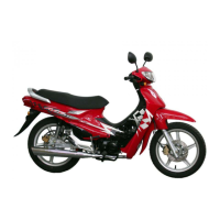
HEADLIGHT VOLTAGE INSPECTION
● Remove the front cover. (⇨4-3)
NOTE
·Check voltage with the headlight coupler connected.
● After starting the engine, place the dimmer switch to
HI and measure the headlight lighting voltage between
the terminals connected to blue (+) and green (-) wires.
● Gradually increase the engine speed and read the
voltage at the specified rpm.
CONTROL VOLTAGE : 14.5
±
0.5V / 5,000rpm
TOOL : DIGITAL TESTER
NOTE
·Measurement is performed in AC range.
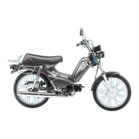
REGULATOR/RECTIFIER INSPECTION
HARNESS SIDE CIRCUIT INSPECTION
● Remove the front cover. (⇨4-3 )
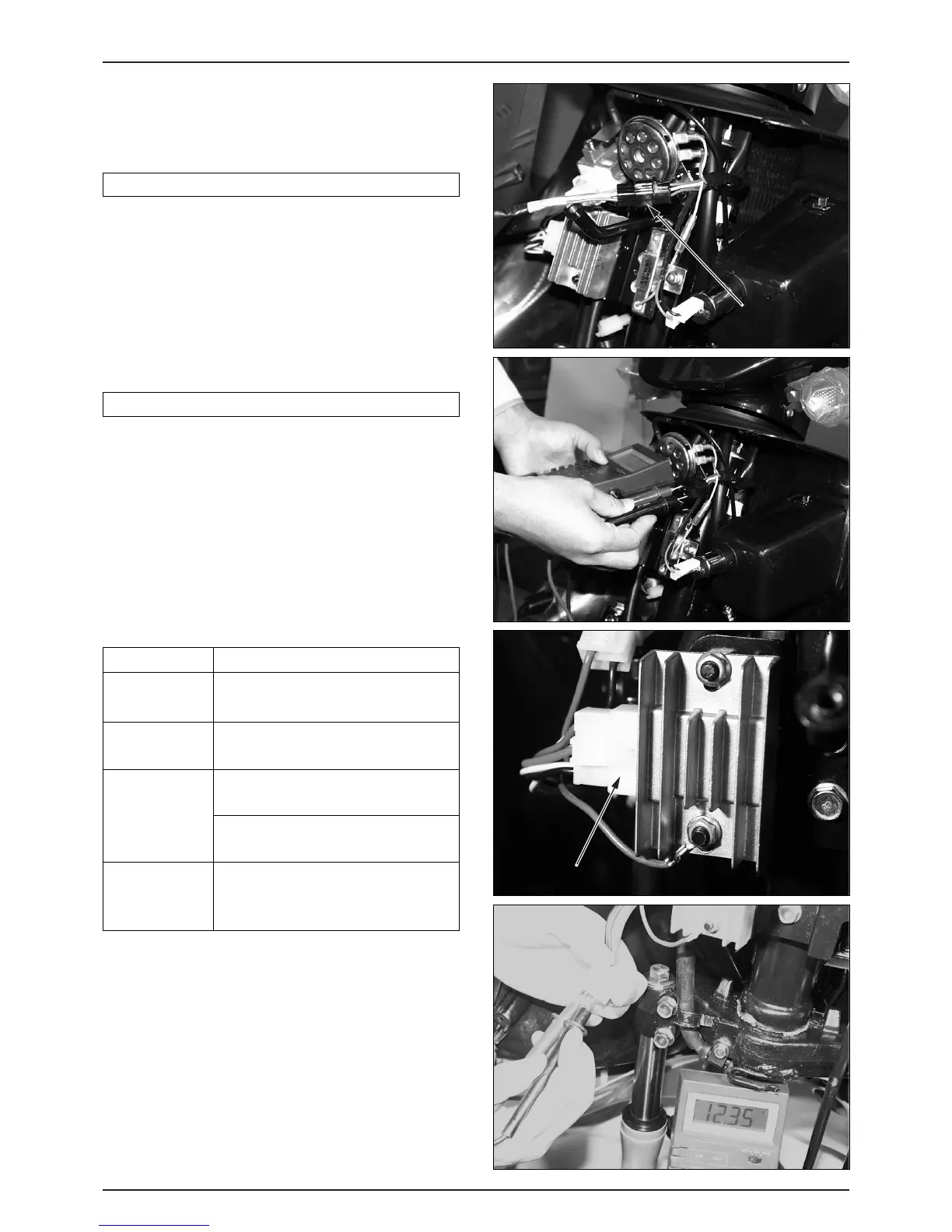
● Remove the coupler of the regulator/rectifier and
inspect the wiring circuits at each terminal of the main
harness coupler.
Inspection Items
● If there is an abnormality in the diagnosis above, check
the following :
-Battery wire →Broken wire harness (repair or replace)
-Ground wire →Broken wire harness (repair or replace)
-Charging coil wire →Check the charging coil of the
A.C generator.
● If the resistance value of the A.C generator is normal,
check for a broken or shorted wire harness between the
regulator rectifier and A.C generator or for poor
connection at A.C generator coupler.
15-6
BATTERY/CHARGING SYSTEM
Check that there is voltage between
battery line (+) and ground line.
Check continuity between ground and
frame.
Check that the resistance of the coil is
within the specified range. (1.0~1.5Ω)
Check not continuity between coil and
frame.
Check that there is battery voltage
between voltage detection line (+) and
ground wire when the ignition is ON.
ITEM INSPECTION
BATTERY
WIRE(RED)
GROUND
WIRE(GREEN)
CHARGING
COIL WIRE
(YELLOW)
VOLTAGE
DETECTION
LINE(BLACK)
 Loading...