CDI UNIT INSPECTION
CDI IGNITION CIRCUIT INSPECTION
NOTE
·Follow the steps described in the troubleshooting
flow chart when servicing the ignition system.
● Release the seat lock with the main key.
● Remove the luggage box. (⇨4-4)
● Disconnect the coupler from the CDI unit, and check the
ignition system circuits from the wiring coupler side.
Inspection Items
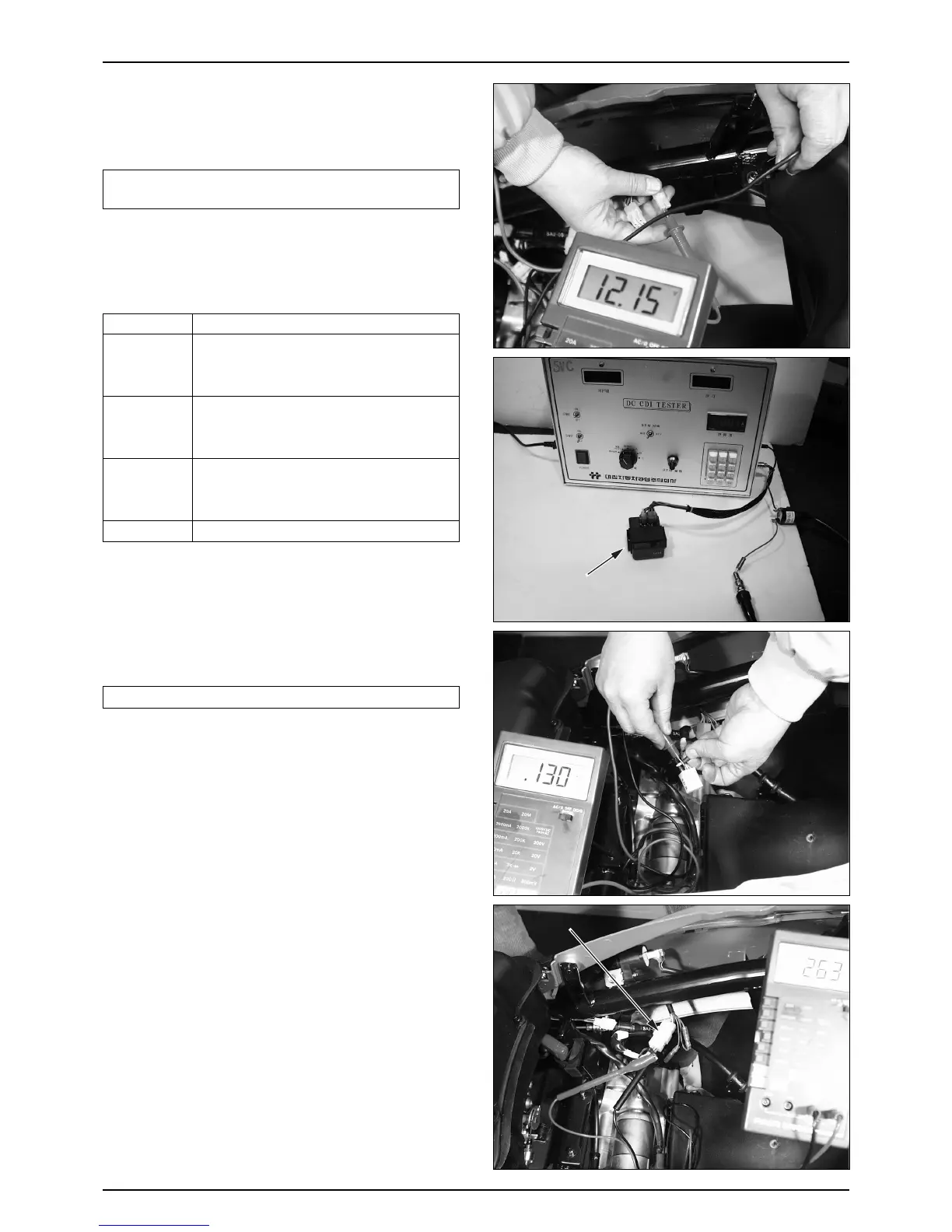
● If there are a normality in the diagonosis above, and if
there is no spark at plug, check the CDI unit and
ignition coil by using a CDI tester.
TOOLS : CDI TESTER
DIGITAL TESTER
NOTE
·Read tester manual carefully prior to using the tester.
● Replace the CDI unit if faulty.
● Install in the reverse order of removal.
PULSE GENERATOR INSPECTION
RESISTANCE MEASUREMENT
● Release the seat lock with the main key.
● Remove the luggage box. (⇨4-4)
● Disconnect the A.C generator 4P coupler and the blue /
yellow wire connector.
● Measure the resistance between the green and blue / yellow.
STANDARD VALUE : 90~150
Ω
(20
℃
)
PVA MEASUREMENT
● Disconnect the A.C generator blue / yellow wire connector.
● Connect the peak voltage adaptor probes to the pulse
generator wire terminal of the wire harness side
connector and ground.
● Crank the engine with the kick starter or starter motor
and measure the peak voltage of pulse generator.
PEAK VOLTAGE : OVER 1.5V
TOOL : PVA MULTI TESTER
● Install in the reverse order of removal.
ITEM
GROUND WIRE
IGNITION COIL
(PRIMARY COIL)
PULSE
GENERATOR
MAIN
SWITCH
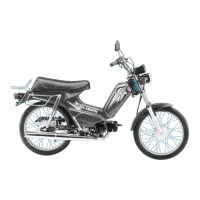
Check that there is battery voltage between
main switch wire (black) and ground wire
when the ignition is ON
Check that the resistance of coil (between blue /
yellow and green) is within the specified range.
( 90~150Ω, 20℃)
Check that the resistance of coil (between black
/ yellow and green) is within the specified range.
( 0.1~0.2Ω, 20℃)
Check continuity between ground and frame.
INSPECTION
 Loading...