16-1
16. IGNITION SYSTEM
SERVICE INFORMATION
GENERAL SAFETY
● Follow the steps described in the troubleshooting flow chart when servicing the ignition system.
● The CDI unit may be damage if dropped. Also, if the connector is disconnected when current is flowing, the excessive
voltage may damage the unit. Always turn off the ignition switch before servicing.
● The CDI unit use an electrically controlled ignition timing system. No adjustments can be made to the ignition timing.
● Use spark plug of the correct heat range. Using spark plug with an incorrect heat range can damage the engine.
● Connect the same color cords. Pay particular attention to colors prior to removing wiring. Connect the same color
couplers.
● A faulty ignition system is often related to poorly connected connectors. Check those connections before proceeding.
● This manual gives explanations on inspections to receive peak voltage. As inspections for coil resistance values are also
included, it may be difficult to make a correct determination.
● Conduct inspection on the main switch by referring to the wiring diagram continuity chart. (⇨chapter 19 )
SPECIFICATIONS
16
SERVICE INFORMATION
········
16-1
IGNITION DEVICES LOCATION
··
16-2
TROUBLESHOOTING
··········
16-3
CDI UNIT INSPECTION
········
16-7
PULSE GENERATOR INSPECTION
··
16-4
IGNITION COIL INSPECTION
····
16-5
IGNITION TIMING INSPECTION
··
16-6
SIDE STAND IGNITION
CUT-OFF SWITCH
··········
·
16-6
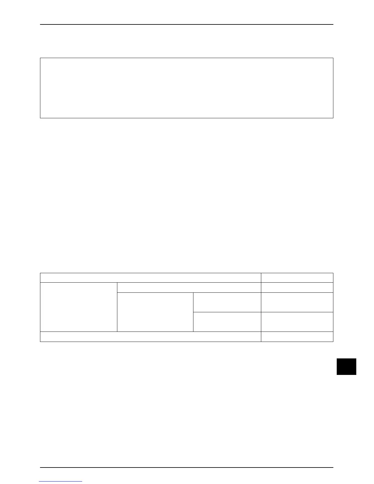
ITEM STANDARD VALUE
IGNITION COIL
RESISTANCE VALUE 20
℃
SECONDARY COIL
PRIMARY COIL
0.1 ~ 0.2 Ω
7.3 ~ 11 ㏀
3.6 ~ 4.6 ㏀
90 ~ 150 Ω
WITH PLUG CAP
WITHOUT PLUG CAP
PULSE GENERATOR COIL RESISTANCE VALUE 20
℃
TOOLS
DIGITAL TESTER
PVA MULTI-TESTER
CDI TESTER
 Loading...