5. Programming on the device
5.3 Circuit diagram elements
5.3.4 Coils
Coils are the actuating mechanisms of relays. The results of the wiring are trans-
ferred to the coils when the device is in RUN mode. These switch to the On (1) or Off
(0) state according to these results. The options for setting output and marker relays
are listed with the description of each coil function.
A easyE4 device is provided with different types of relays and function blocks which
can be wired in a circuit diagram via their coils (inputs).
Coil functions
You can configure the switching behavior of relays with coil functions and para-
meters.
If you want to map coils from your circuit diagram to the
easyE4 device, use the coils with a contactor function in your
device!
The following coil functions are available for all coils:
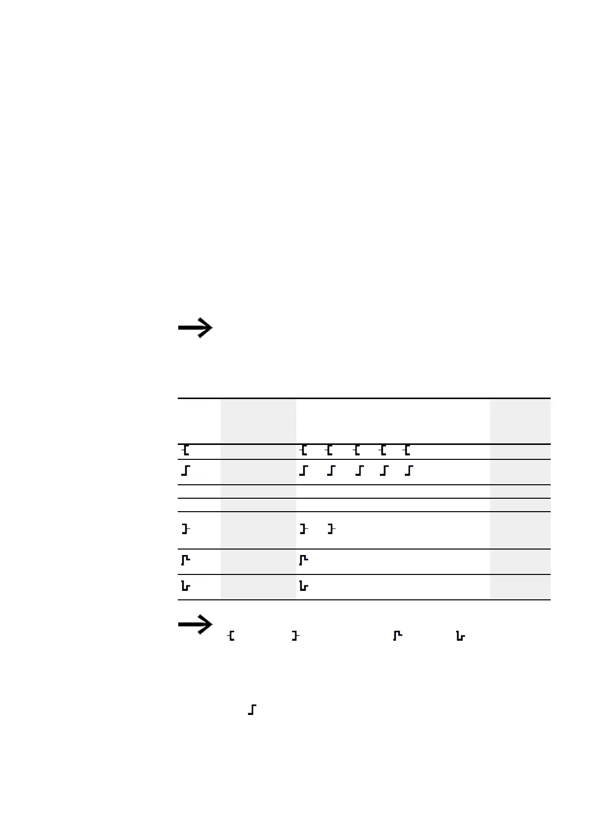
Display Coil function Example → Page
Contactor function
Q01, D02, S04, :01, M07,..
→ page 192
Impulse relay func-
tion
Q03, M04, D08, S07, :01,..
→ page 192
S
Set
SQ08,SM02,SD03,SS04..
→ page 193
R
Reset
RQ04,RM05,RD07,RS03..
→ page 193
Contactor function
with
negated result
Q04, M96..
→ page 194
Cycle pulse
on rising edge
M01..
→ page 194
Cycle pulse
on falling edge
M42..
→ page 195
Tab. 76: Coil function
With non-retentive coil functions such as
(contactor), (negated contactor), (rising) and (falling edge eval-
uation): Each coil must only be used once. The last coil in the circuit dia-
gram determines the state of the relay. Exception: When working with
jumps, the same coil can be used twice.
Retentive coil functions such as
S, R, can be used several times.
The available coil functions for the various function blocks are described in the rel-
evant sections. Please refer to → Section "Working with function blocks", page 217
easyE402/24 MN050009ENEaton.com
191
 Loading...