EasyManua.ls Logo

Eaton easyE4 User Manual

Eaton easyE4
879 pages
To Next Page IconTo Next Page
To Previous Page IconTo Previous Page
Page #326 background imageLoading...
Page #326 background image
6. Function blocks
6.1 Manufacturer function blocks
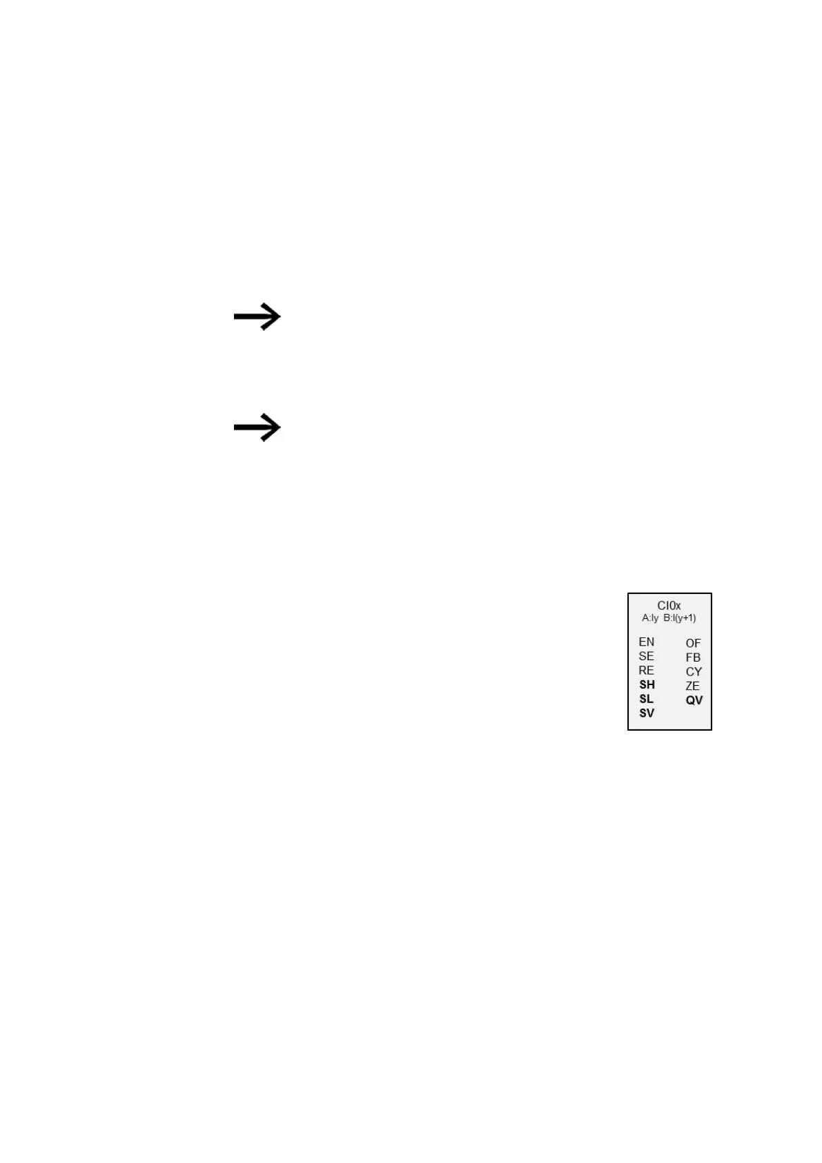
6.1.2.4 CI - Incremental counter
CI function blocks can be used to quickly count rising and falling edges forward and
backward. This counting is independent of the cycle time.
You can set a lower and higher limit as comparison values for the incremental value
counter, as well as a start value.
There are two incremental counters available.
Square wave count pulses are required to ensure a 1:1 mark to space
ratio.
The signals at channels A and B must have an offset of 90°; otherwise
the count direction will not be detected.
The maximum count frequency is 5000 Hz.
Note that the digital inputs I1 to I4 are permanently assigned to the incre-
mental counter function blocks provided:
l
I1: Counter input for counter CI01, channel A.
l
I2: Counter input for counter CI01, channel B.
l
I3: Counter input for counter CI02, channel A.
l
I4: Counter input for counter CI02, channel B.
General information
easyE4 base devices provide 2 high-speed incremental encoder
counters, CI01 through CI02. The high-speed up and down coun-
ters are internally hardwired with the digital inputs I01...I02 or
I03...I04 and operate independently of the cycle time.
Operating principle
Incremental counters interpret rising and falling edges in order to identify the count
direction. The count will be in the direction of the rising and falling edges.
The counter wiring must observe the following digital device input assignment:
I01 Counter input for the counter CI01 channel A.
I02 Counter input for counter CI01 channel B
I03 Counter input for counter CI02 channel A
I04 Counter input for counter CI02 channel B
The contacts will switch according to the actual value. The appropriate function
block outputs switch according to the actual value determined. The counter relays
enable a preset start value to be defined at the SV input.
Only square wave signals are permissible.
322
easyE402/24 MN050009ENEaton.com

Table of Contents

Other manuals for Eaton easyE4

Question and Answer IconNeed help?

Do you have a question about the Eaton easyE4 and is the answer not in the manual?

Eaton easyE4 Specifications

General IconGeneral
MountingDIN Rail
Protection ClassIP20
Number of Digital OutputsUp to 16
Number of Analog InputsUp to 8 (depending on configuration)
Number of Analog OutputsUp to 2
Communication PortsEthernet, RS-232, RS-485
Programming SoftwareeasySoft
Programming LanguagesLadder Diagram (LD), Function Block Diagram (FBD)
Power Supply Voltage24 V DC
Operating Temperature+55 °C
Dimensions90 x
Memory128 kB program memory

Summary

Before starting with the installation

Installation requires qualified electrician

Safety requirement for installation, emphasizing the need for a qualified electrician.

Verify isolation from the supply

Ensuring the device is safely disconnected from the power supply before proceeding.

1. Description of easyE4 control relay

1.1 Use as intended

Defines the intended applications and purpose of the easyE4 control relay.

1.8 easySoft 8 programming software

Details about the programming software used for easyE4 devices.

1.9 Safety regulations

General safety rules and mandatory requirements for handling the device.

2. Installation

2.1 Prerequisites for the location of use

Requirements for the installation environment and location of use for the device.

2.3 Mounting

Instructions and guidelines for physically mounting the easyE4 control relays and expansions.

2.4 Connection terminals

Details on terminal types and connection procedures for easyE4 devices.

3. Commissioning

3.1 Initial commissioning

Step-by-step guide for the initial setup and commissioning of the easyE4 device.

3.5 Establishing an Ethernet connection and transferring a program or visualization project

Procedure for establishing an Ethernet connection and transferring projects.

3.8 Updating firmware

Instructions for updating firmware on base devices, expansion devices, and communication modules.

4. Operation

4.1 Base device with display and buttons

Details on operating base devices with displays and buttons.

4.6 Transfer program to the easyE4 device

Options for transferring programs to the easyE4 device via memory card or Ethernet.

5. Programming on the device

6. Function blocks

6.1 Manufacturer function blocks

Pre-defined solutions for common programming tasks, including timer, counter, and arithmetic functions.

7. System settings

7.7 Update

Procedures for loading new firmware onto easyE4 devices and communication modules.

7.9 Setting the startup behavior

Defining how the easyE4 device responds upon power-up.

7.14 Security – password protection

Setting up passwords and password-protected areas.

8. How easyE4 works internally

8.1 Program execution

Explains how programs are executed using LD, FBD, ST, and EDP languages.

9. Operating system diagnostic messages

10. easyE4 communication Connection to other devices

10.7 Establish a connection to the device

Step-by-step guide to establishing an online connection with the easyE4 device.

10.11 Secure communication with certificates

Ensuring secure communication using certificates for easyE4 devices.

10.15 Setting up the e-mail function

Configuration of email alerts for events like errors or operating state changes.

10.17 Modbus TCP

Details on configuring Modbus TCP client and server settings for easyE4.

11. Faults

12. Maintenance

Related product manuals