2. Installation
2.4 Connection terminals
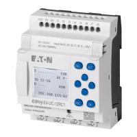
2.4.4 Connect digital inputs
The inputs of the easyE4 devices switch electronically.
Once you have connected a contact via an input terminal, you can reuse it as a con-
tact in your circuit diagram as often as you like.
Connect the contacts, for example buttons or switches, to the input terminals of the
easyE4 device.
12, 24 V DC/24 V AC
24 V DC
0 V/N
InI3I2I10 V
InI3I2I10 V
EASY-E4-DC-12TC1(P)
EASY-E4-DC-12TCX1(P)
EASY-E4-UC-12RC1(P)
EASY-E4-UC-12RCX1(P)
InI3I2I1N
EASY-E4-AC-12RC1
(P)
EASY-E4-AC-12RCX1(P)
UC:
DC:
AC:
100 -
240 V AC/DC (cULus 100 - 110 V DC)
L
Ue
Fig. 19: Connecting the digital inputs on base devices
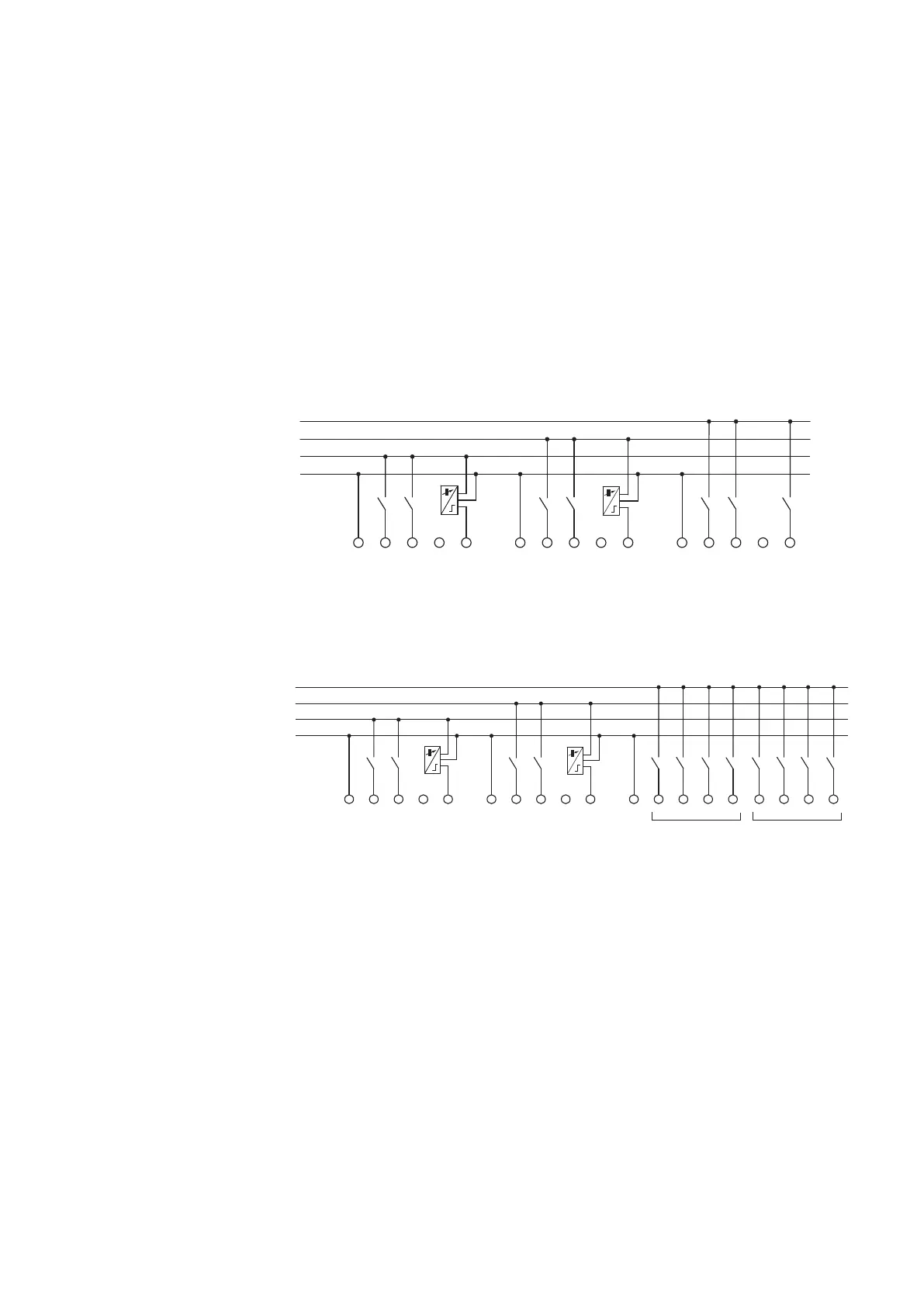
12, 24 V DC/24 V AC
24 V DC
0 V/N
InI3I2I10 V
InI3I2I10 V
EASY-E4-DC-8TE1(P)
EASY-E4-DC-16TE1(P)
EASY-E4-UC-8RE1(P)
EASY-E4-UC-16RE1(P)
I4I3I2I1N
EASY-E4-AC-8RE1
(P)
EASY-E4-AC-16RE1(P)
UC:
DC:
I8I7I6I5
AC:
100 - 240 V AC/DC (cULus 100 - 110 V DC)
L
Ue
Fig. 20: Connecting the digital inputs on expansions
As per the hardware characteristics, base devices have 8 digital inputs available (I1
– I8)
Meanwhile, expansion devices feature 4 (I1 – I4) or 8 (I1 – I8) inputs.
See also
→ Section "Connect digital AC inputs", page 47
easyE402/24 MN050009ENEaton.com
71
 Loading...