List of Figures
List of Figures
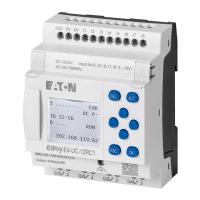
Fig. 1: Device model with EASY-E4-...-12...C1(P) display and button controls or
with EASY-E4-...-12...CX1(P) LED display for diagnostics 26
Fig. 2: Device models in 4SU 28
Fig. 3: Device models in 2SU 28
Fig. 4: AC input with suppression diode easyE4 AC 47
Fig. 5: AC input with ballast M22-XLED-T 48
Fig. 6: Increased input current with X2 safety capacitor 48
Fig. 7: Limitation of the input current through resistors 49
Fig. 8: An increase in input current with M22-XLED230-T 49
Fig. 9: Min. clearance of 3 cm 59
Fig. 10: Assembling a base device with expansions 60
Fig. 11: Assembling the base device with an easy communication module as
example EASY-COM-SWD-C1 61
Fig. 12: Installation on IEC/EN 60715 mounting rail 62
Fig. 13: Inserting a fastening bracket. 64
Fig. 14: Example: Screw mounting for a 4U device 64
Fig. 15: Remove adjacent connectors 65
Fig. 16: Dismantling 65
Fig. 17: Connecting the power supply for base devices 68
Fig. 18: Connecting the power supply for expansions 69
Fig. 19: Connecting the digital inputs on base devices 71
Fig. 20: Connecting the digital inputs on expansions 71
Fig. 21: Connect digital counter inputs 73
Fig. 22: Connecting the analog inputs on base devices 74
Fig. 23: Connecting relay outputs 75
Fig. 24: Connecting base device transistor outputs 76
Fig. 25: Connecting expansion device transistor outputs 76
Fig. 26: Inductive load with suppressor circuit 77
Fig. 27: Device parameters tab, using the EASY-E4-DC-6AE1 as an example 78
Fig. 28: Connecting analog inputs EASY-E4-DC-6AE1(P) 79
Fig. 29: Connecting analog outputs EASY-E4-DC-6AE1(P) 79
easyE402/24 MN050009ENEaton.com
855
 Loading...