1. Description of easyE4 control relay
1.10 Engineering
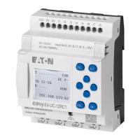
Fig. 5: AC input with ballast M22-XLED-T
Switching the I7/I8 inputs on AC base devices
Neon lamps with a maximum residual current of 2 mA / 1 mA at 230V/115V can be
connected to I7 and I8.
WARNING
Do not use reed relay contacts on I7, I8. These may burn or melt due
to the high inrush current of I7, I8.
Two-wire proximity switches have a residual current in the 0 state. If this residual
current is too high, the device only detects the 1 state at the input.
With two-wire proximity switches or sensors with similar residual current con-
sumption use therefore the inputs I7 and I8.
Use an additional input circuit if several inputs are required with a higher input cur-
rent.
For all inputs - except for the high current inputs I7, I8 on the base device - the fol-
lowing applies:
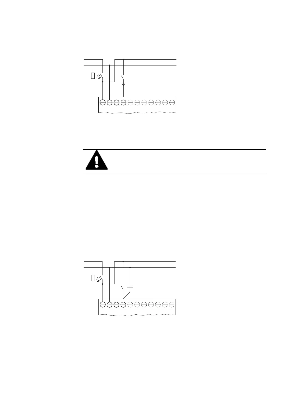
The following input circuit can be used in order to prevent interference and also
when using two-wire proximity switches:
L
N
100 nF/275 V ~
F1
L N N
I1
Fig. 6: Increased input current with X2 safety capacitor
l
When an X2 safety condenser is in the circuit, the decay time of the input
extends, from 100 nF by 75 (45) ms at 230V (115V).
l
The current is increased by 6 mA at 230V/50 Hz and by 4 mA at 115v/60 Hz.
To limit the engagement current, you can include a resistor in series in the circuit.
48
easyE402/24 MN050009ENEaton.com
 Loading...