2. Installation
2.4 Connection terminals
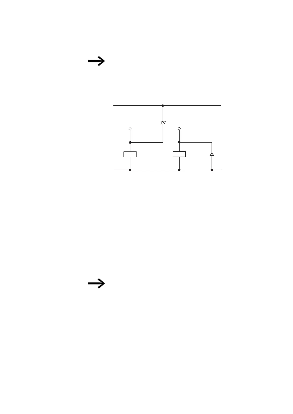
Depending on the actual inductive load (I, L):
If the +24 V
DC
power supply is switched off via a contact in the event of
an emergency stop, and if more than one driven output with an inductive
load can be switched off, you must provide these inductive loads with a
suppressor circuit.
+ 24 V H
Q
U
emax
< U
Z
< 33
V
0 V H
Q
Fig. 26: Inductive load with suppressor circuit
2.4.7.1 Transistor output behavior in the event of a short circuit/overload
The following applies to easyE4 devices with transistor outputs:
In the event of a short circuit or overload at a transistor output, this output will switch
off and a general fault alarm ID (please refer to fault IDs) will be set to 1. The output
will switch back on up to the maximum temperature after a cooling time that depends
on the ambient temperature and the current level. If the fault continues, the output
will switch off and on until the fault is rectified or the power supply is switched off.
2.4.7.2 Connecting outputs in parallel
Only outputs of the same group (Q1 to Q4 or Q5 to Q8) can be connected in parallel;
e.g. Q1 and Q3 or Q5, Q7 and Q8. Parallel switched outputs must be simultaneously
energized.
If the outputs are not switched on and off automatically, or if outputs
from both groups are connected in parallel, this may result in mal-
functions such as those occurring in the case of overloads.
easyE402/24 MN050009ENEaton.com
77
 Loading...