2. Installation
2.4 Connection terminals
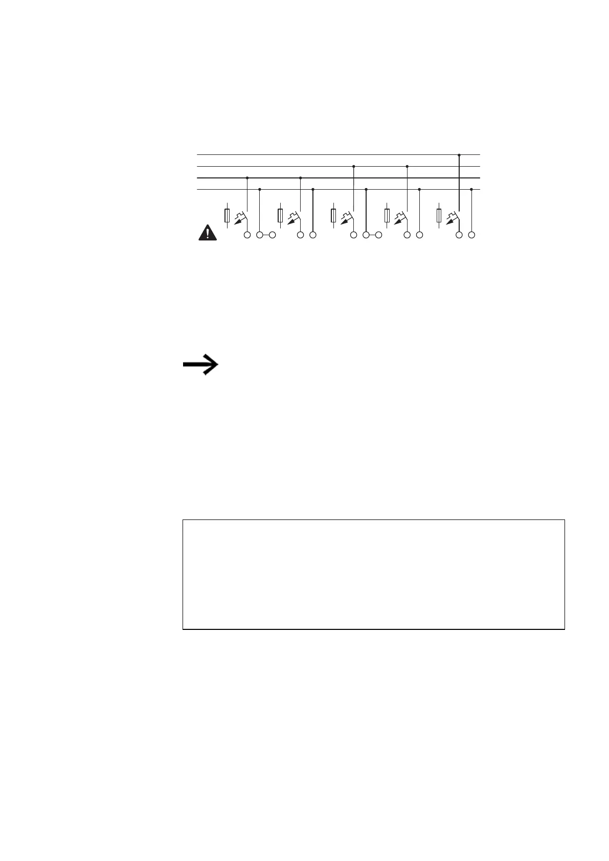
12, 24 V DC/24 V AC
24 V DC
UC:
DC:
0 V/ N
F1 > 1 A
+24 V 0 V +24 V 0 V + UC 0 V + UC 0 V
EASY-E4-DC-8TE1(P)
EASY-E4-DC-6AE1(P)
EASY-E4-UC-8RE1(P)
EASY-E4-DC-16-TE1(P)
EASY-E4-UC-16RE1(P)
L N
EASY-E4-AC-8RE1(P)
EASY-E4-AC-16RE1(P)
EASY-E4-DC-4PE1(P)
AC:
100 - 240 V AC/DC (cULus 100 - 110 V DC)
L
Ue
Fig. 18: Connecting the power supply for expansions
The way in which the power supply should be connected to the easy
communication module is described in the corresponding section:
EASY-COM-SWD-…
→ Section "Connecting the power supply through POW/AUX", page 756
EASY-COM-RTU-… → Section "Connecting the power supply ", page 770
System test
The devices run a system test after the supply voltage has been switched on.
The system test lasts 1 s for the base device. After this time elapses, the device will
enter RUN or STOP mode depending on the specific device and configured settings.
NOTICE
When the basic devices and expansion units are switched on, they
behave like a capacitor, so that an inrush current higher than the
rated input current is present. Take this inrush current into account
when designing the electrical equipment by using slow fuses and suit-
able switches. Never use reed relay contacts to switch the power sup-
ply as these may burn or stick.
You can find the required connection specifications for your device model from the
corresponding data sheet, → Section "Technical data", page 825
easyE402/24 MN050009ENEaton.com
69
 Loading...