1. Description of easyE4 control relay
1.10 Engineering
1.10.3 Notes for connection of EASY-E4-AC-... devices
1.10.3.1 Connect digital AC inputs
CAUTION
Connect the inputs on EASY-E4-AC-... devices according to the VDE,
IEC, UL and CSA safety requirements. The same phase conductor to
which the device power supply is connected should be used for the
supply of the inputs. EASY-E4-...Otherwise, the device will not detect
the switching level or may be destroyed by overvoltage.
For the inputs I5-I8 of the EASY-E4-AC-16RE1(P) expansion devices, one of the other
two phases can also be used.
During wiring, make sure to meet all cable protection requirements. → Section "Cable
protection", page 68.
Input signal voltage range
l
OFF signal: 0 to 40 V
l
ON signal: 79 V to 264 V
Input current
l
I1 I1 to I6 basic devices, I1 to I8 expansion devices: 0.5 mA/0.25 mA at 230 V/115 V
l
I7, I8 basic devices: 6 mA/4 mA at 230 V/115 V
In addition, the following applies to I1–I6 on base devices and for the AC exten-
sions:
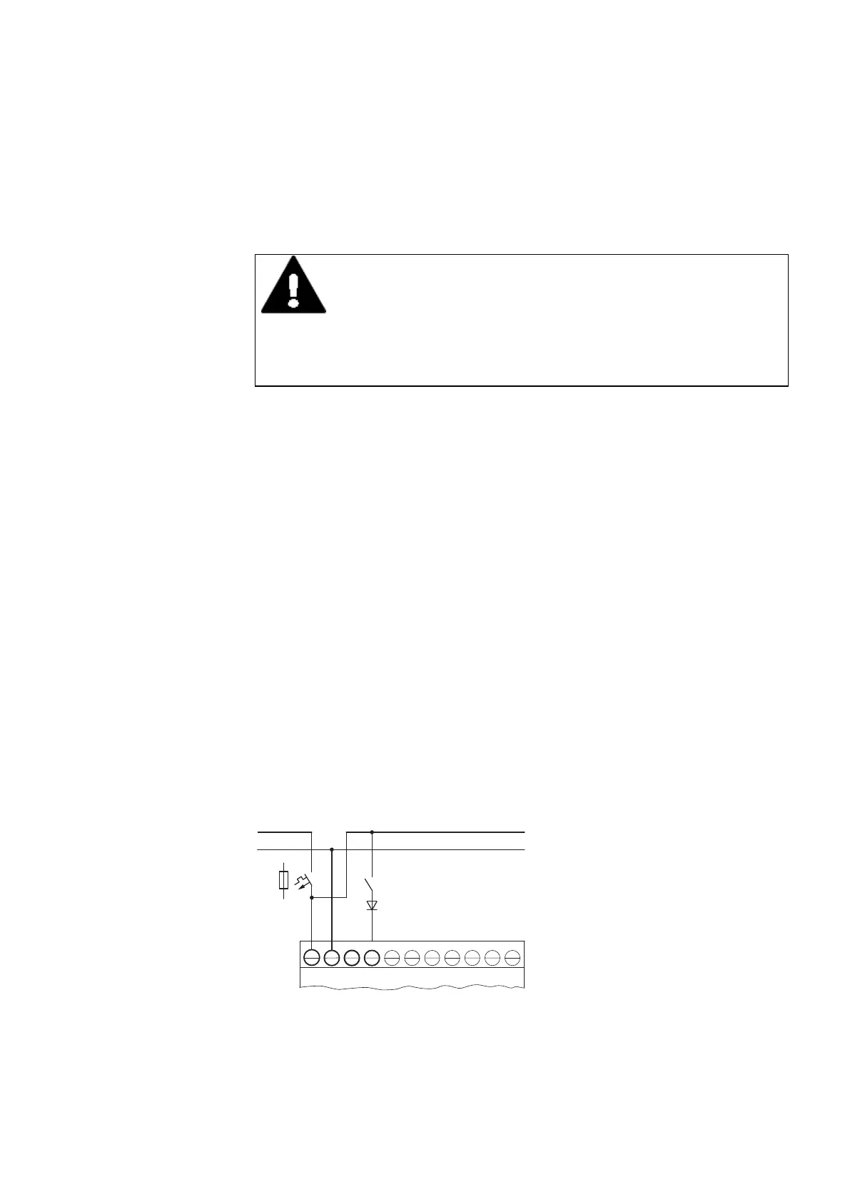
On longer wires, you connect a diode (e.g. 1N4007, 1A) with minimum 1000 V reverse
voltage in series to the device input. Make sure that the diode points to the input, i.e.
that the cathode of the diode is connected to the input, otherwise the device will not
recognize state 1.
Fig. 4: AC input with suppression diode easyE4 AC
Alternatively, ballast M22-XLED-T (item no. 231079) can be used as a diode.
easyE402/24 MN050009ENEaton.com
47
 Loading...